Rotary moving workbench

A technology for moving workbenches and workbench bases, applied to workbenches, manufacturing tools, metal processing equipment, etc., can solve problems such as complex mechanical connection devices, complex control circuits, and low transmission efficiency, and improve positioning accuracy and response speed , fast response, short transmission line

Active Publication Date: 2019-12-20
LIAONING UNIVERSITY OF TECHNOLOGY
View PDF7 Cites 0 Cited by
  • Summary
  • Abstract
  • Description
  • Claims
  • Application Information

AI Technical Summary

Problems solved by technology

Features of machine tool control device: simple control principle, complex mechanical connection device, complex control circuit, low transmission efficiency, large friction during work, etc.

Method used


Image

  • Rotary moving workbench
  • Rotary moving workbench
  • Rotary moving workbench

Examples


Embodiment Construction

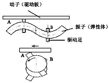
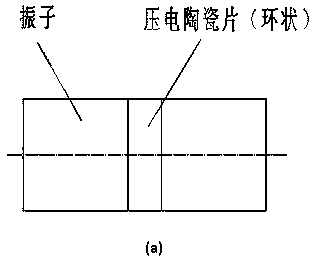
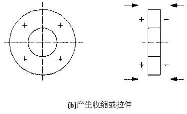
[0024] The following is a detailed description in conjunction with the accompanying drawings: As shown in the figure, in order to facilitate the description of the working principle, the driving device is simplified, and the ring-shaped driving foot is simplified into a single tooth shape, such as figure 1 As shown, when the piezoelectric ceramic group A passes through a periodic alternating electrical signal, the vibrator forms a second-order bending vibration mode, and the driving foot contacts the vibrator to exert pressure on the vibrator. When the piezoelectric ceramic group B is energized, the vibrator forms a torsional mode At this time, the bending and torsion are compounded, and under the action of friction, the mover can be freely driven to move back and forth.

[0025] The support seat 19 is fixed on the workbench base 1 by the set screw B24, the clutch device 15 is fixed on the support seat 19 by the positioning disc 23 and the positioning bolt B20, the clutch devic...


PUM


Abstract

A rotary moving workbench comprises a clutch device, a driving device, a self-locking device, linear sliding blocks, linear sliding rails, a linear grating ruler B and a circular grating ruler A, wherein the rotary moving workbench is fixed on a rotary circular ring through screws. The rotary moving workbench has the advantages that the problems of a complex mechanical connecting device, a complexcontrol circuit, low transmission efficiency, large friction in the working process and the like are solved, the structure is more reasonable, a piezoelectric ceramic is used as a piezoelectric vibrator to form a torsional mode, the conversion rate of energy is efficient under the action of friction, the working efficiency of the workbench is further improved, and the positioning accuracy and theresponse speed of the system are improved.

Description

technical field [0001] The invention belongs to a rotary mobile workbench. Background technique [0002] The workbench plays a huge role in the production process of the enterprise, which is convenient for product storage, transportation and processing. The transportation workbench is the guarantee to realize the mechanization and automatic transportation and processing of products. [0003] The general principles of various workbenches are the same, and the movement direction of the workbench is controlled by contacting the limit or reversing device on the workbench with the reversing switch. They all use weak electricity to control strong electricity. It's just that the numerical control is done through the feedback device. The motor (serving motor or AC / DC motor) is transmitted to the lead screw (ordinary screw or ball screw) to complete the movement of the workbench. The working principle of the traditional workbench is relatively simple, but it is more difficult to r...

Claims


Application Information

Patent Timeline
Patent Type & Authority Applications(China)
IPC IPC(8): B25H1/00B25H1/14B23Q1/25
CPCB25H1/00B25H1/14B23Q1/25
Inventor 王宏祥张欣弛王玉振
Owner LIAONING UNIVERSITY OF TECHNOLOGY
Why Eureka
Try Eureka