

Process for producing fluorinated vinyl ether
- Summary
- Abstract
- Description
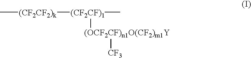
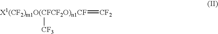
- Claims
- Application Information
AI Technical Summary
Benefits of technology
Problems solved by technology
Method used
Image

Examples
example 1
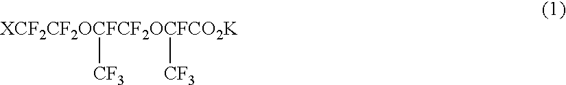
[0063]Into a 100-ml flask were introduced 14.5 g of potassium carbonate and 20 ml of ethylene glycol dimethyl ether, and 48.8 g of a carboxylic acid fluoride (purity 96% by weight) of general formula (3) wherein X=—CO2CH3 was added dropwise thereto at 40° C. The resulting mixture was continuously stirred as it was for 2 hours, after which the solvent was distilled off under reduced pressure and the residue was dried in a vacuum at 100° C. to obtain a solid potassium salt containing KF. The complete conversion of the carboxylic acid fluoride to the corresponding potassium salt was confirmed by 19F-NMR. The flask was equipped with a distillation head and a condenser and heated as it was up to 200° C. at atmospheric pressure, and the heating was continued at 200° C. until distilling-out of a liquid ceased. During the heating, the potassium salt retained its solid state. By gas chromatography, 38.3 g of the liquid recovered was analyzed to find that it contained a vinyl ether of general...
example 5
[0068]Into a 200-ml three-necked flask was introduced 27.6 g of potassium carbonate, and 48.8 g of the same carboxylic acid fluoride (purity 95% by weight) as in Example 1 was added dropwise thereto at 100° C. The reaction was continued for another 2 hours, whereupon the whole reaction mixture was solidified. At this stage, the complete conversion of the carboxylic acid fluoride to the corresponding potassium salt was confirmed by 19F-NMR. The flask was equipped with a distillation head and a condenser and heated as it was up to 200° C. to carry out a pyrolysis reaction. By gas chromatography, 39.5 g of the resulting liquid was analyzed to find that the liquid contained 91% by weight of the vinyl ether (yield: 89%) and 4% by weight of a diester of formula (V).
example 9
[0072]Into a 200-ml three-necked flask were introduced 51.2 g of a carboxylic acid fluoride (purity: 98% by weight) of the general formula (3) wherein X=—SO2F and 20 ml of ethylene glycol dimethyl ether, and 14.5 g of potassium carbonate was added thereto in small portions with heating at 60° C. In addition, the reaction mixture was continuously stirred at 60° C. for 30 minutes and then the solvent was distilled off under reduced pressure to obtain a solid potassium salt containing KF. The conversion rate calculated on the basis of 19F-NMR was 96%. The flask was equipped with a distillation head and a condenser and heated as it was up to 220° C. at atmospheric pressure, and the heating was continued at 220° C. until distilling-out of a liquid ceased. During the heating, the potassium salt retained its solid state. By gas chromatography, 42.9 g of the liquid recovered was analyzed to find that it contained 84% by weight of a vinyl ether of the general formula (2) wherein X=—SO2F (cru...
PUM
| Property | Measurement | Unit |
|---|---|---|
| Fraction | aaaaa | aaaaa |
| Percent by mass | aaaaa | aaaaa |
| Percent by mass | aaaaa | aaaaa |
Abstract
Description
Claims
Application Information