Dust removal device for downhole drill machine for coal mine exploitation

A technology of down-the-hole drilling rig and dust removal device, which is applied in the direction of construction, etc., which can solve the problems of affecting environmental quality, inability to fully absorb dust, and limited dust collection range of dust collection equipment, so as to improve dust removal efficiency, dust removal effect is obvious, and speed up the contact speed Effect

Active Publication Date: 2019-12-20
HENAN UNIV OF URBAN CONSTR
View PDF9 Cites 2 Cited by
  • Summary
  • Abstract
  • Description
  • Claims
  • Application Information

AI Technical Summary

Problems solved by technology

[0003] The current down-the-hole drilling rigs are generally equipped with dust collection equipment, but due to the limited dust collection range of the dust collection equipment, the dust generated during the drilling operation will quickly spread to the surroundings and cannot be completely absorbed, affecting the environmental quality

Method used


Image

  • Dust removal device for downhole drill machine for coal mine exploitation
  • Dust removal device for downhole drill machine for coal mine exploitation
  • Dust removal device for downhole drill machine for coal mine exploitation

Examples


Embodiment 1

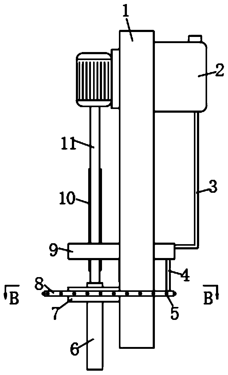
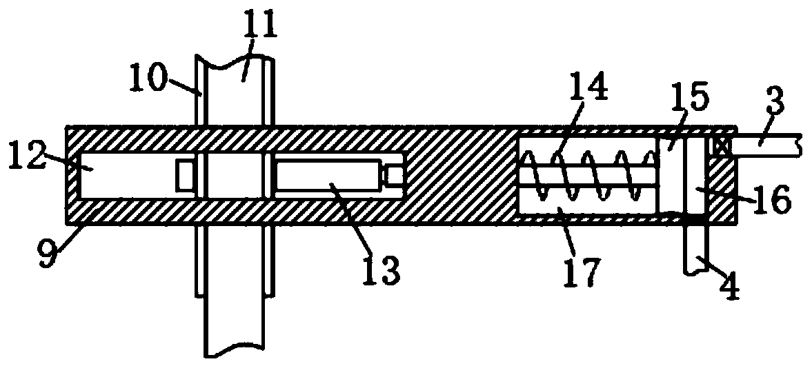
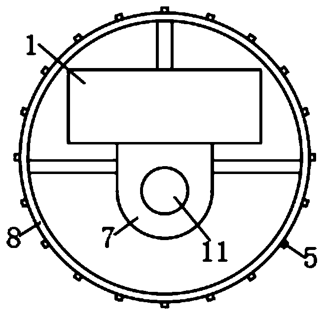
[0024] refer to Figure 1-4 , a dust removal device for a down-the-hole drilling rig used in coal mine development, comprising a drill bit support arm 1 installed on the front side of the down-the-hole drilling rig, and a hydraulic lifting device, a motor, a drill rod 11, a drill bit 6 and a limiter are installed on the drill bit support arm 1 Block 7, the side wall of drill bit support arm 1 runs through and is fixedly connected with device plate 9, is provided with device cavity 12 in device plate 9, is provided with cam 13 in device cavity 12, and the bottom of cam 13 is fixedly connected with ring-shaped slide rail 20, ring-shaped The slide rail 20 is slidably connected with the inner bottom of the device chamber 12 to ensure the normal rotation of the cam 13. The axis of the cam 13 is provided with a circular opening 18, the drill pipe 11 runs through the circular opening 18, and the two side walls of the drill pipe 11 are fixed with The slide bar 10 and the opposite inne...

Embodiment 2

[0029] refer to Figure 5-6 The difference between this embodiment and Embodiment 1 is that the lower end of the limit block 7 is fixedly connected with an annular plate 24 sleeved on the outside of the drill bit 6, the inner side of the annular plate 24 is close to the outer wall of the drill bit 6, and the inner side of the annular plate 24 The side wall is provided with an annular cavity 25, and the outer wall of the annular plate 24 is evenly distributed with a plurality of air outlet holes 23 communicating with the annular cavity 25, and the outer wall of the device plate 9 is provided with a suction pipe 22 communicating with the second cavity 17, and The cavity 17 communicates with the annular cavity 25 through the air outlet pipe 21, the air outlet pipe 21 runs through the limit block 7, and a one-way valve is installed in the air outlet pipe 21 and the suction pipe 22, and the one-way valve in the air outlet pipe 21 makes the air only It can be discharged from the sec...


PUM


Abstract

The invention discloses a dust removal device for a downhole drill machine for coal mine exploitation. The dust removal device comprises a drill bit support arm arranged on the front side of the downhole drill machine, and a hydraulic lifting device, a motor, a drill rod, a drill bit and a limiting block are arranged on the drill bit support arm. The side wall of the drill bit support arm is fixedly connected with a device plate in a penetrating manner. A device cavity is formed in the device plate and internally provided with a cam. The axis position of the cam is provided with a circular port. The drill rod penetrates through the circular port. Sliding strips are fixed to the two side walls of the drill rod. The opposite inner walls of the circular port are provided with sliding ways matched with the sliding strips. A cavity is formed in the device plate and internally provided with a piston. The piston divides the cavity into a first cavity body and a second cavity body. The side wall of the piston is fixedly connected with an abutting rod extending into the device cavity. The dust removal device is reasonable in structure, drill rod rotation can be utilized as a drive source, awater source is constantly sprayed out, a water cover is formed, scattered dust can be effectively absorbed, and the dust removal efficiency is high.

Description

technical field [0001] The invention relates to the technical field of down-the-hole drilling rigs, in particular to a dust removal device for down-the-hole drilling rigs used in coal mine development. Background technique [0002] In coal mining, it is necessary to use down-the-hole drilling rigs for drilling operations. At present, more advanced down-the-hole drilling rigs generally adopt a hydraulic drilling method, which drives the drill rod and the drill bit to rotate through a motor to drill, and then adjusts the depth of the drill hole through a hydraulic press. [0003] The current down-the-hole drilling rigs are generally equipped with dust collection equipment, but due to the limited dust collection range of the dust collection equipment, the dust generated during the drilling operation will quickly spread to the surroundings and cannot be completely absorbed, which affects the environmental quality. [0004] So there is an urgent need for a dust removal device fo...

Claims


Application Information

Patent Timeline
Patent Type & Authority Applications(China)
IPC IPC(8): E21B21/01
CPCE21B21/01
Inventor 万祥云贾炳王洪义娄全王文军黄战峰彭荣富许哲曹智伟
Owner HENAN UNIV OF URBAN CONSTR
Why Eureka
Try Eureka