A secondary swirl energy dissipation device for dam cone valves

A technology of energy dissipation devices and cone valves, which is applied in the field of energy dissipation devices and energy dissipation devices for dam cone valves, and can solve the problems of low energy dissipation efficiency of cone valves

Active Publication Date: 2021-04-23
黑龙江省水利水电集团有限公司
View PDF7 Cites 0 Cited by
  • Summary
  • Abstract
  • Description
  • Claims
  • Application Information

AI Technical Summary

Problems solved by technology

[0002] Existing dam cone valves generally use air discharge or submerged discharge, and the high-speed water flow at the outlet of the cone valve is eliminated by means of external energy dissipation measures, but the energy dissipation efficiency of the cone valve itself is very low

Method used


Image

  • A secondary swirl energy dissipation device for dam cone valves
  • A secondary swirl energy dissipation device for dam cone valves

Examples


specific Embodiment approach 1

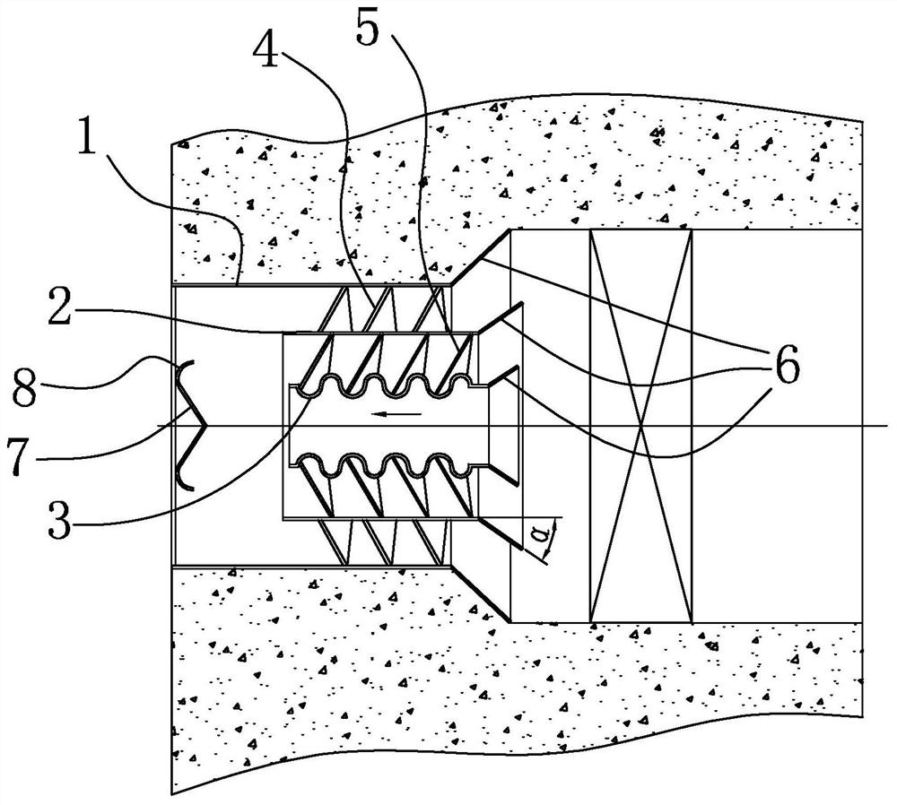
[0016] Specific implementation mode one: combine figure 1 with figure 2 To illustrate this embodiment, this embodiment includes a housing 1, a first sleeve 2, a second sleeve 3, a first helical blade 4 and a second helical blade 5;

[0017] The housing 1, the first sleeve 2 and the second sleeve 3 are sequentially arranged from the outside to the inside and a cavity is formed between the adjacent two, the housing 1, the first sleeve 2 and the second sleeve 3 are concentric, The casing 1, the first sleeve 2 and the second sleeve 3 are all arranged on one side of the outlet of the cone valve, and the cavity between the casing 1 and the first sleeve 2 is provided with a first helical blade 4, and the second A helical blade 4 is fixed on the inner wall of the housing 1, and the cavity between the first sleeve 2 and the second sleeve 3 is provided with a second helical blade 5, and the rotation of the first helical blade 4 and the second helical blade 5 On the contrary, the surf...

specific Embodiment approach 2

[0019] Specific implementation mode two: combination figure 1 To describe this embodiment, in this embodiment, the end of the outlet side of the first sleeve 2 protrudes from the outlet end of the second sleeve 3 .

[0020] In this way, the water from the shell 1 and the first sleeve 2 and the water from the first sleeve 2 and the second sleeve 3 are first mixed to form water with lower energy and finally mixed with the water from the second sleeve 3 Mix to reduce the energy of the second sleeve 3.

[0021] Other compositions and connections are the same as in the first embodiment.

specific Embodiment approach 3

[0022] Specific implementation mode three: combination figure 1 To describe this embodiment, the middle section of the second sleeve 3 in this embodiment is a corrugated sleeve.

[0023] The corrugated sleeve is set so that the water passing through the inner and outer surfaces of the second sleeve 3 generates a swirling flow, and the swirling flow disturbs the water in the second sleeve 3 longitudinally, and at the same time, the effluent water after the swirling flow has a negative impact on the first sleeve 2 and the second sleeve. The outlet water after swirling between the two sleeves 3 plays a transverse shearing effect to eliminate part of the energy of the water; meanwhile, the surface area of ​​the corrugated sleeve is larger than that of the straight tube, which can eliminate part of the energy of the water through friction.

[0024] Other compositions and connections are the same as in the first embodiment.


PUM


Abstract

A secondary swirl energy dissipation device for dam cone valves, belonging to the technical field of water conservancy and hydropower, to solve the problem that the existing cone valves use external energy dissipation, and the existing cone valves themselves have low energy dissipation efficiency The problem. The present invention comprises a housing, a first sleeve, a second sleeve, a first helical blade and a second helical blade; the housing, the first sleeve and the second sleeve are sequentially arranged from outside to inside and adjacent A cavity is formed, the housing, the first sleeve and the second sleeve are concentric, the housing, the first sleeve and the second sleeve are all arranged on one side of the outlet of the cone valve, the housing and the first sleeve The cavity between the first and second sleeves is provided with a first helical blade, the first helical blade is fixed on the inner wall of the housing, the cavity between the first sleeve and the second sleeve is provided with a second helical blade, the first helical blade Contrary to the direction of rotation of the second helical blade, the surfaces of the first helical blade and the second helical blade are provided with a plurality of protrusions, and a conical deflector is provided on the side of the outlet of the second sleeve.

Description

technical field [0001] The invention belongs to the technical field of water conservancy and hydropower, and relates to an energy dissipation device, in particular to an energy dissipation device for a dam cone valve. Background technique [0002] Existing dam cone valves generally use air discharge or submerged discharge, and the high-speed water flow at the outlet of the cone valve is eliminated by means of external energy dissipation measures, but the energy dissipation efficiency of the cone valve itself is very low. Contents of the invention [0003] In order to solve the above problems, the present invention provides a secondary swirl energy dissipation device for a dam cone valve. [0004] The technical scheme that the present invention takes for solving the problems of the technologies described above is: [0005] It includes a housing, a first sleeve, a second sleeve, a first helical blade and a second helical blade; [0006] The housing, the first sleeve and th...

Claims


Application Information

Patent Timeline
Patent Type & Authority Patents(China)
IPC IPC(8): F16K47/08
CPCF16K47/08
Inventor 杜维松于等文徐龙军王祥国张玉才梁锦江
Owner 黑龙江省水利水电集团有限公司
Why Eureka
Try Eureka