Wave and tide actuated renewable energy pump

a renewable energy and wave-actuated technology, applied in the direction of pump, positive displacement liquid engine, machine/engine, etc., can solve the problems of insufficient rainwater and insufficient keeping, and achieve the effect of simple and robustness

Inactive Publication Date: 2012-01-31
HILL JR RICHARD NEWTON
View PDF3 Cites 25 Cited by
  • Summary
  • Abstract
  • Description
  • Claims
  • Application Information

AI Technical Summary

Benefits of technology

[0009]2. Creation of Hydro-electric power: Either directly pumping the water to a submerged turbine with surge tank or by pumping the water behind a dam and allowing it to flow out uniformly to hydro-electric turbines. The surplus energy should make coastal states the most financially solvent and prosperous states in the US while consumer energy bills drop to an insignificant cost and energy rationing is eliminated.
[0010]3. Desalination Of Sea water: The energy pump can be the source of power for conventional desalination plants, dramatically reducing the cost of operation as energy consumption will now be a minimal factor, making desalination of sea water practical in fresh water deprived parts of the world.
[0011]4. Seafood Farming: Pump sea water to a levied area and raise fish or shrimp, etc. When ready for harvest, let the water out through the levee's flood gate and scoop up the fish or shrimp by hand or mechanically, eliminating the need for shrimp and fish trawlers, while guaranteeing a full harvest. This is similar to what is being done in some other countries now, using their high tides to capture the water behind levees.
[0013]6. In the “dead” areas of the ocean: Where oxygen has been depleted, killing off marine life, the pump would be used to circulate oxygen rich water in, eliminating the “dead” area of the sea.

Problems solved by technology

An additional volume of buoyancy is added sufficient to insure the buoy travels upward, as close as possible, to the same speed of the wave in its' up and down motion but not sufficient enough to keep from positioning buoy within the desired angle of repose in ocean currents with the aid of additional mooring lines if necessary.
The resultant evaporation shall form clouds and the prevailing winds will carry the moisture to the next natural or man made barrier, causing rain to fall.

Method used


Image

  • Wave and tide actuated renewable energy pump
  • Wave and tide actuated renewable energy pump
  • Wave and tide actuated renewable energy pump

Examples


Embodiment Construction

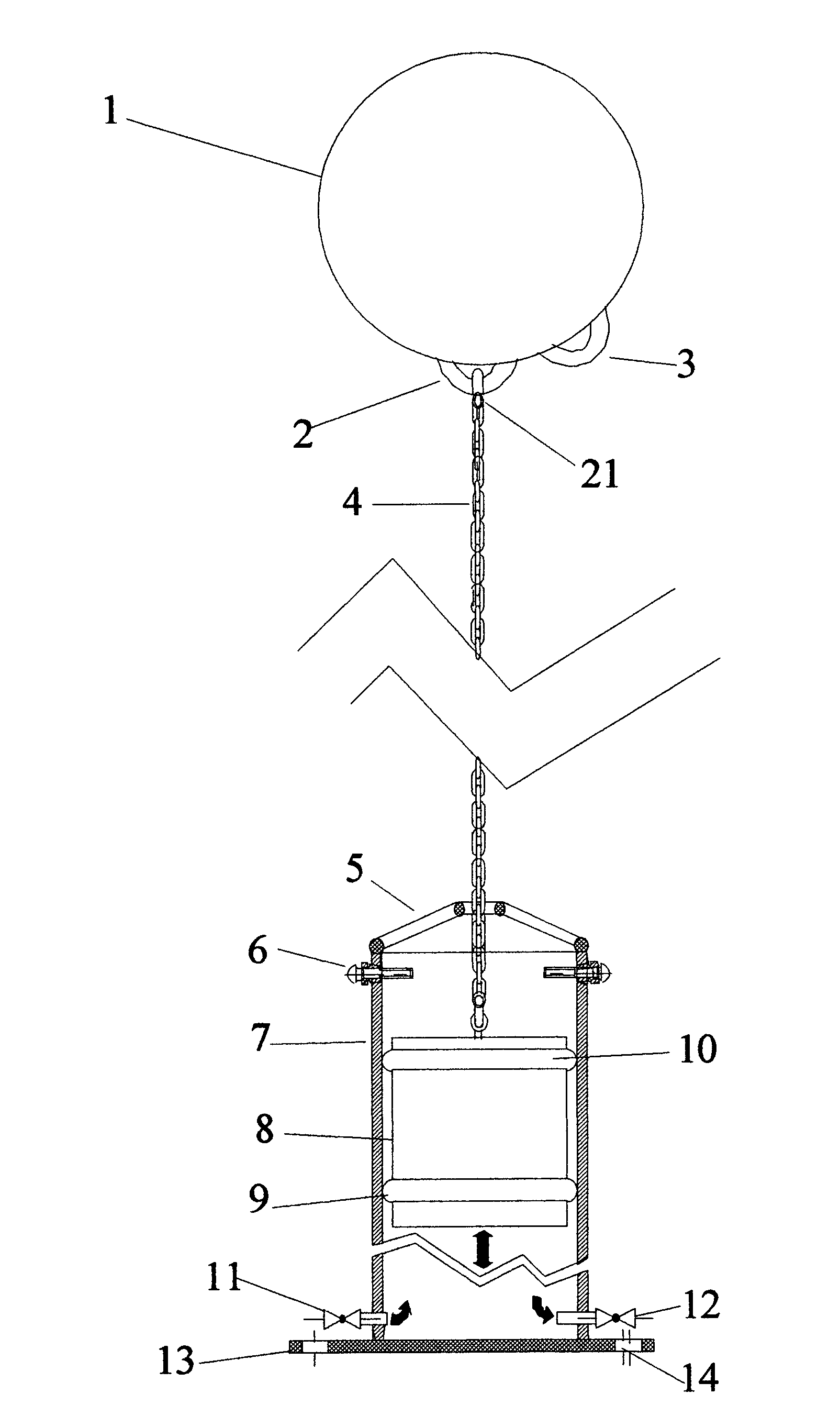
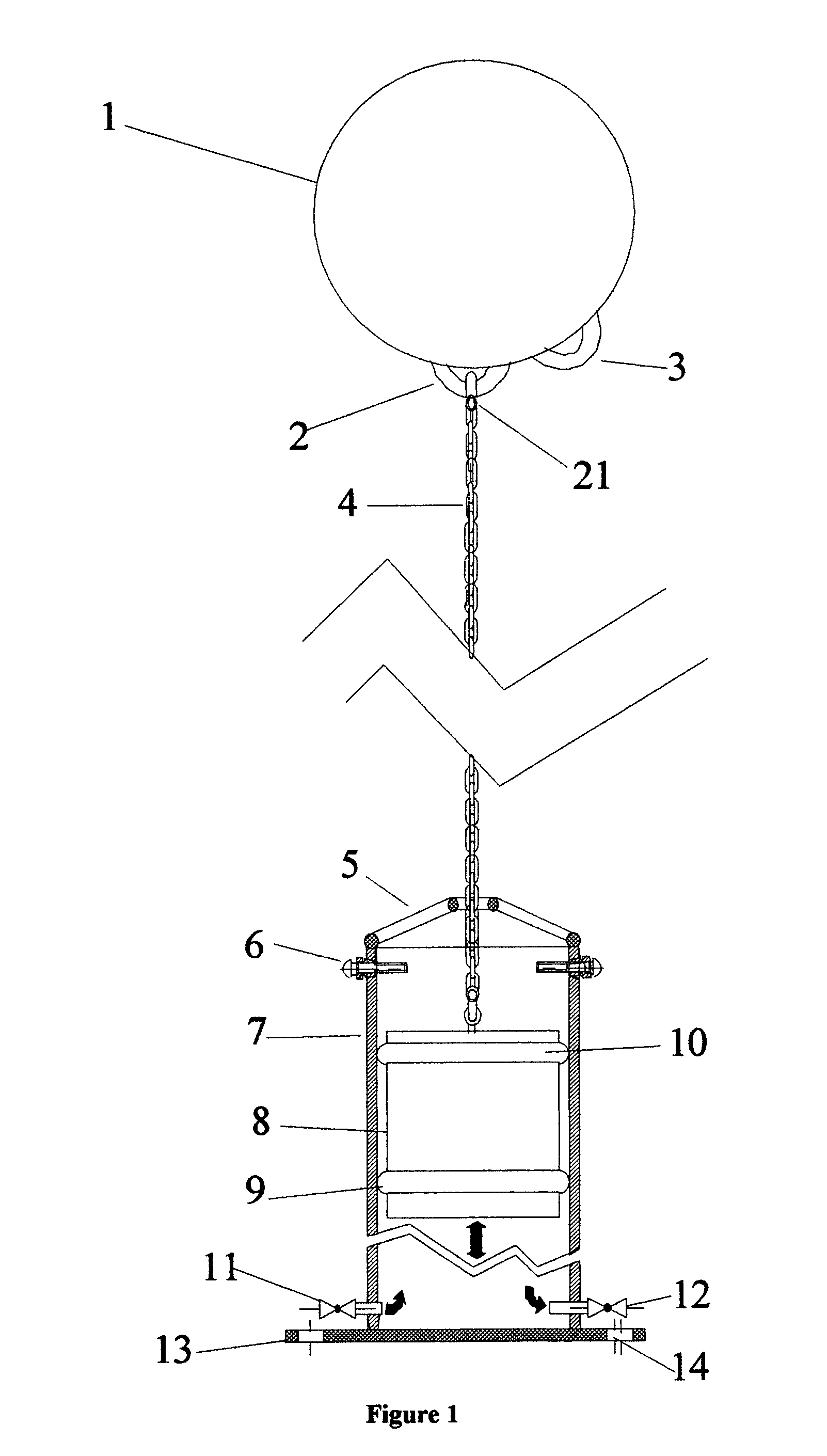
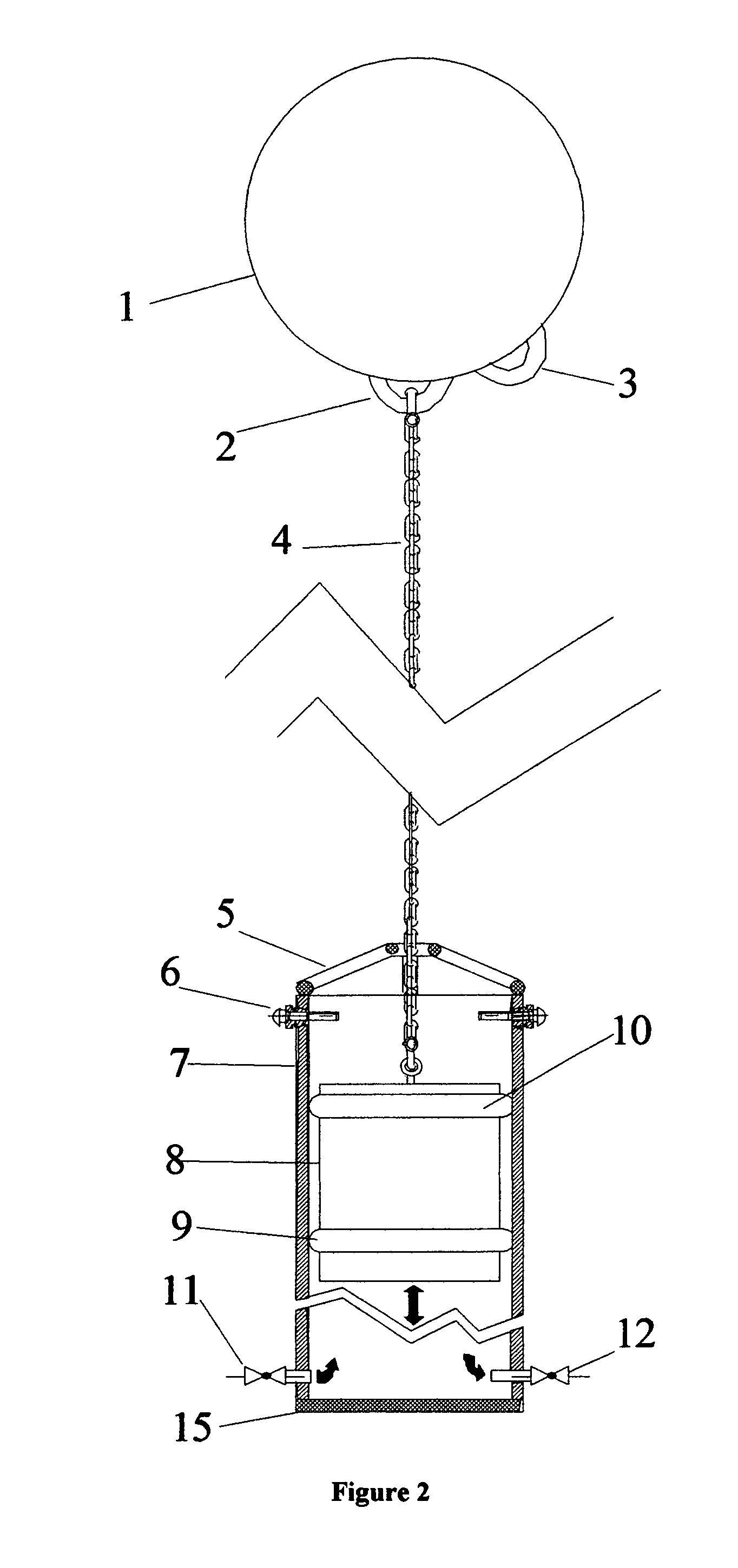
[0026]The buoy (1), shown in FIGS. 1, 2, 9 and 10 is sufficient in size to capture as much wave energy as is practical. The buoy (1) has a lifting eye or anchorage (2) in which a shackle (21) or clevis is secured. A chain or cable (4), is attached to shackle (21). An additional mooring eye (3) is provided for anchorage to tether the buoy (1) against strong prevailing currents such as the Gulf and Japanese Streams off the respective east and west coasts of the US.

[0027]A second shackle or clevis (16) is attached to eyebolt (17) shown in FIG. 3. The eyebolt (17) is imbedded in the weighted piston (8), FIGS. 3 and 5. The ballast weighted piston (8), may have one or more sealing rings (9), FIGS. 1, 2, 3, 4, 5 and 6. The bottom ring (9) provides the primary seal while the upper ring (10) stabilizes the direction of travel as well as providing a second seal. An air vent (18) with check valve ball (19) and air vent chamber (34), FIG. 5 is provided in the weighted piston (8) to prevent air ...


PUM


Abstract

A pumping mechanism that utilizes wave and tidal energy to operate. The mechanism relies on the depth of the fluid or sea and the length of the pump cylinder to accommodate shifting wave and tide patterns. Alternatively, the mechanism is imbedded or placed in an excavation in the fluid or ocean bed of sufficient depth and width to accommodate the piston cylinder, its' easing and the shifting wave and tide conditions. The invention relies on a buoy or float for the lift of a ballast weighted piston and the ballast weighted piston, when descending, provides the means of creating pressure on the water entrapped in the cylinder, thus causing a pumping action. The pump may be used individually or in concert with other pumps. The pump is intended to move large or small volumes of water at high or low pressures, singularly or in concert with other pumps.

Description

CROSS REFERENCE TO RELATED APPLICATIONS[0001]This is a Continuation In part based on Utility patent application Ser. No. 10 / 600,701 filed Jun. 23, 2003 now abandoned and Provisional Patent Application Ser. No. 60 / 390,421, filed Jun. 24, 2002, by current applicant, Richard Newton Hill, Jr., entitled “WAVE AND TIDE ACTUATED PUMP.” Applicant claims use of this prior filing date.BACKGROUND OF INVENTION[0002]This wave and tide actuated pump will satisfy most of the world's energy requirements. By harnessing ½ of 1% of the renewable energy in the ocean waves, the entire world's energy needs can be met. This pump will replace oil, gas, coal and nuclear power as primary sources of energy. It is these sources of energy that are causing pending and future conflicts in the Middle Fast and the world.[0003]More importantly, by the year 2025 the world will run out of food and water sufficient to support the world's population. This pump again provides the answer.[0004]This pump is the best deterr...

Claims


Application Information

Patent Timeline
Patent Type & Authority Patents(United States)
IPC IPC(8): F04B17/00F03B13/18
CPCF04B17/00F04B35/004F04B47/06F04B49/025Y02E10/38Y02E10/30
Inventor HILL, JR., RICHARD NEWTON
Owner HILL JR RICHARD NEWTON
Why Eureka
Try Eureka