

A Corner Cube Folded Cavity Laser
A corner cube prism and laser technology, applied in the laser field, can solve problems such as easy misalignment of lasers and reduced stability of lasers, and achieve the effects of ensuring anti-misalignment characteristics, simple structure, and increasing cavity length
- Summary
- Abstract
- Description
- Claims
- Application Information
AI Technical Summary
Problems solved by technology
Method used
Image

Examples
Embodiment 1
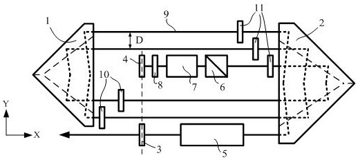
[0023] refer to figure 1 As shown, a kind of opposed corner cube folded cavity laser disclosed in the present invention is composed of a first corner cube prism 1, a second corner cube prism 2, an output mirror 3, a total reflection mirror 4, a pump module 5, and a polarizer 6. A Q switch 7, a first λ / 4 wave plate 8, a second λ / 4 wave plate 10, and a third λ / 4 wave plate 11. The first corner cube prism 1, the second corner cube prism 2, the output mirror 3 and the total reflection mirror 4 form the opposite corner cube resonator cavity of the laser, the output mirror 3 and the total reflection mirror 4 are coplanar, and in the first corner cube between prism 1 and second corner cube prism 2. The first corner cube prism 1 is opposite to the light passing surface of the second corner cube prism 2, and the sequentially arranged polarizer 6, Q switch 7 and first λ / 4 wave plate 8 are arranged on the second corner cube prism 2 and the total reflection mirror 4, the pump module 5 i...
Embodiment 2
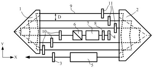
[0027] refer to figure 2 As shown, as yet another embodiment, the difference from Embodiment 1 is that the output mirror 3 and the total reflection mirror 4 are between the first corner cube prism 1 and the second corner cube prism 2 but not in the same plane. A corner cube prism 1, a second corner cube prism 2, an output mirror 3, and a total reflection mirror 4 form the opposite corner cube prism resonant cavity of the laser. The polarizer 6, the Q switch 7 and the first λ / 4 wave plate 8 arranged in sequence are arranged between the first corner cube prism 1 and the total reflection mirror 4, and the pump module 5 is arranged between the second corner cube prism 2 and the output Between mirrors 3, wherein the second λ / 4 wave plate 10 is arranged between the first corner cube prism 1 and the polarizer 6, and the third λ / 4 wave plate 11 is arranged between the Q switch 7 and the second corner cube prism 2 between.
[0028] Due to the reflection characteristics of the corner...
Embodiment 3
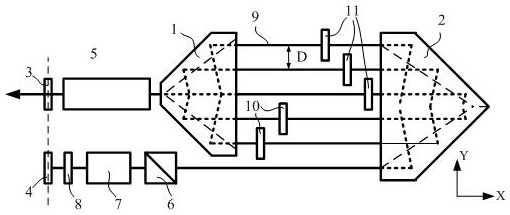
[0030] refer to image 3 As shown, as yet another embodiment, the difference from Embodiment 1 is that the output mirror 3 and the total reflection mirror 4 are arranged on the same side of the first corner cube prism 1 and the second corner cube prism 2 to form opposite corner cubes Prism folding cavity, the output mirror 3 and the total reflection mirror 4 are coplanar, and the polarizer 6, Q switch 7 and first λ / 4 wave plate 8 arranged in sequence are arranged between the second corner cube prism 2 and the total reflection mirror 4 , the pumping module 5 is arranged between the light-transmitting surface of the cutout part and the output mirror 3 . The apex of the first corner cube prism 1 needs to be cut off as a light-transmitting surface, and coated with an anti-reflection film in the laser band.
[0031] Due to the reflection characteristics of the corner cube prism, the resonator of the laser can have an anti-misalignment characteristic. When a certain mechanical defo...
PUM
 Abstract
Description
Claims
Application Information