

Novel folding cavity laser device with opposed right-angle prisms
A right-angle prism and laser technology, applied in the laser field, can solve the problems of increasing the Q-switched pulse width, increasing the volume of the laser, and difficult to precisely control the pulse width, so as to achieve the effect of adjusting and increasing the cavity length.
- Summary
- Abstract
- Description
- Claims
- Application Information
AI Technical Summary
Problems solved by technology
Method used
Image

Examples
Embodiment 1
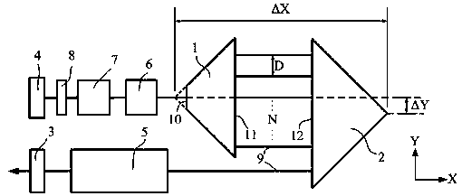
[0018] refer to figure 1 As shown, a folded cavity laser with opposed right-angled prisms disclosed in the present invention consists of a first right-angled prism 1, a second right-angled prism 2, an output mirror 3, a total reflection mirror 4, a pump module 5, a polarizer 6, and a Q The switch 7 and the λ / 4 wave plate 8 are composed. The output mirror 3 and the total reflection mirror 4 are arranged on the outside of the first right-angle prism 1 and the second right-angle prism 2, and the first right-angle prism 1 and the second right-angle prism 2 are provided with the first light-passing surface 11 and the second parallel to each other respectively. The light-passing surface 12, the first right-angle prism 1, the second right-angle prism 2, the output mirror 3, and the total reflection mirror 4 form the opposed right-angle prism resonant cavity of the laser. The pumping module 5 is the gain medium and the pumping source of the laser, and the polarizer 6, the Q switch 7,...
Embodiment 2
[0028] refer to Figure 4 As shown, as yet another embodiment, the difference from Embodiment 1 is that the output mirror 3 and the total reflection mirror 4 are on the same side of the first right-angle prism 1 and the second right-angle prism 2 and are coplanar. The polarizer 6 , the Q switch 7 and the λ / 4 wave plate 8 are arranged between the light-passing surface 10 at the right-angle vertex and the total reflection mirror 4 , and the pump module 5 is arranged between the second light-passing surface 12 and the output mirror 3 .
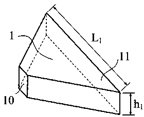
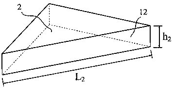
[0029] The thickness of the first rectangular prism 1 is 10 mm, the width of the light-transmitting surface 10 at the apex of the right angle is 6 mm, and the length of the hypotenuse is 56 mm. The thickness of the second rectangular prism 2 is 10 mm, and the length of the hypotenuse is 64 mm. The distance between the right-angle vertices of the first right-angle prism 1 and the right-angle vertices of the second right-angle prism 2 in the X dir...
Embodiment 3
[0032] refer to Figure 5 As shown, as yet another embodiment, the difference from Embodiment 1 is that the output mirror 3 and the total reflection mirror 4 are on opposite sides of the first right-angle prism 1 and the second right-angle prism 2, and polarizers 6 arranged in sequence , Q switch 7 and λ / 4 wave plate 8 are arranged between the first light-passing surface 11 and the total reflection mirror 4 , and the pump module 5 is arranged between the light-passing surface 10 at the right-angle vertex and the output mirror 3 .
[0033] The thickness of the first rectangular prism 1 is 10 mm, the width of the light-transmitting surface 10 at the apex of the right angle is 6 mm, and the length of the hypotenuse is 56 mm. The thickness of the second rectangular prism 2 is 10 mm, and the length of the hypotenuse is 48 mm. The distance between the right-angle vertices of the first right-angle prism 1 and the right-angle vertices of the second right-angle prism 2 in the X direct...
PUM
| Property | Measurement | Unit |
|---|---|---|
| Thickness | aaaaa | aaaaa |
Abstract
Description
Claims
Application Information