Motor cooling structure

A motor cooling and motor shaft technology, applied in cooling/ventilation devices, electrical components, electromechanical devices, etc., can solve the problems affecting the physical and mental health of workers, affecting the stability of motors, polluting the working environment, etc., to avoid howling, Reduce working noise and ensure stable operation

Pending Publication Date: 2019-12-20
ANHUI TONGHUA NEW ENERGY POWER
View PDF0 Cites 5 Cited by
  • Summary
  • Abstract
  • Description
  • Claims
  • Application Information

AI Technical Summary

Problems solved by technology

However, when the airflow in the inner cavity of the housing is blocked by the motor end cover, it will generate turbulent flow and whistling sound, which will seriously poll

Method used


Image

  • Motor cooling structure
  • Motor cooling structure

Examples


Embodiment Construction

[0010] The specific implementation manner of the present invention will be further described in detail below by describing the embodiments in conjunction with the accompanying drawings.

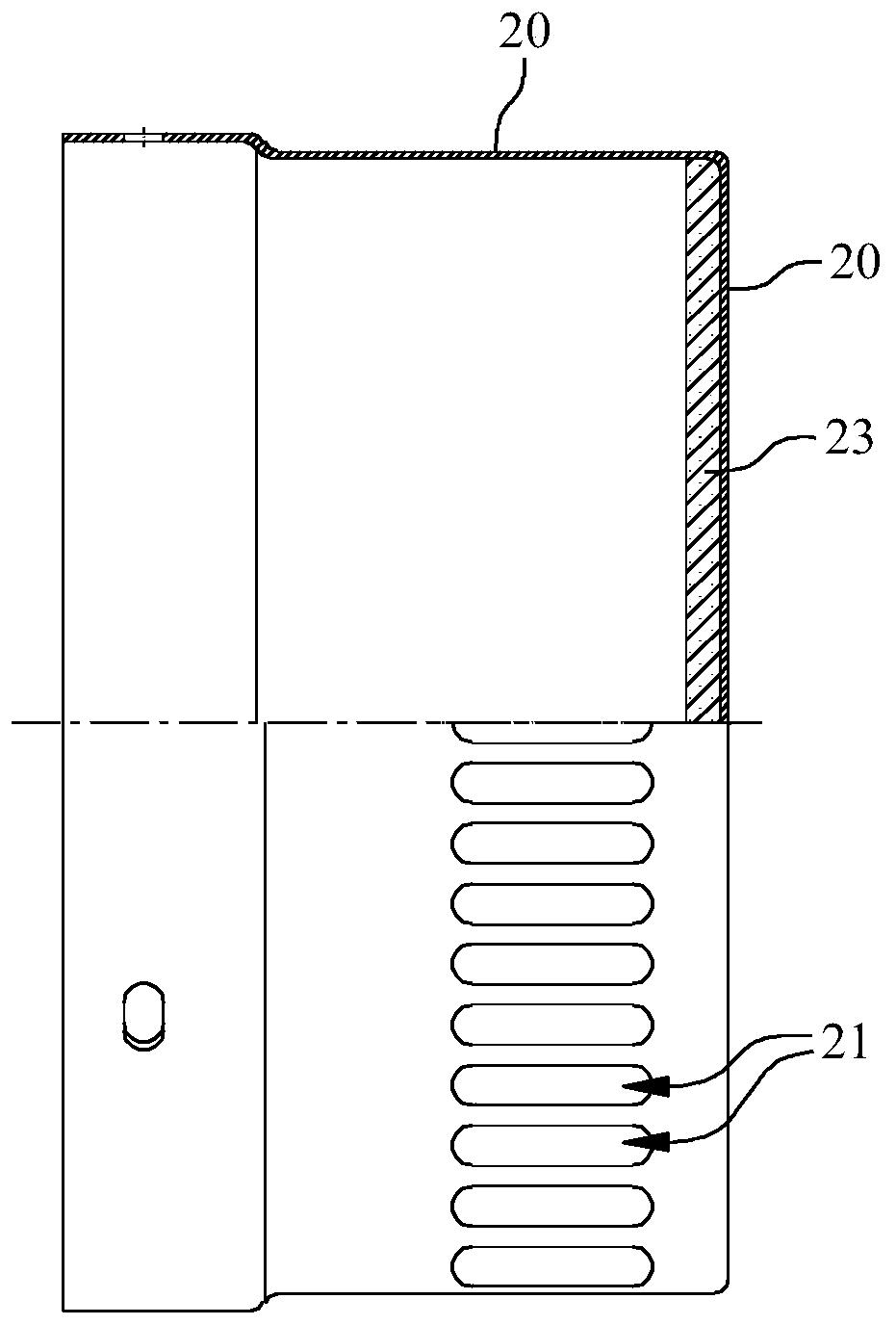
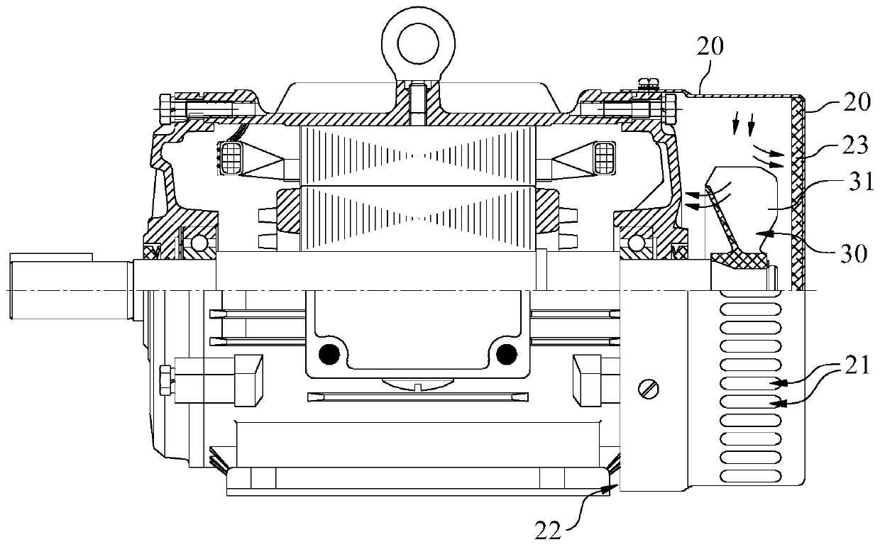
[0011] A motor cooling structure, comprising a motor housing 11, a cylindrical cover 20 is provided at the end of the motor housing 11, and an impeller 30 is arranged in a cavity formed by the cover 20 and the motor housing 11, The side wall of the cover 20 is provided with an air inlet 21 , the gap between the side wall of the cover 20 and the motor housing 11 forms an air outlet 22 , and the inner wall of the bottom wall of the cover 20 is provided with a sound-absorbing layer 23 .

[0012] When in use, the cooling gas enters the inner cavity of the housing from the side wall of the housing 20 , then flows along the axial direction of the housing 20 and is discharged from the air outlet 21 . If the cooling gas is blocked by the motor housing 11 to generate an airflow moving away from the ai...


PUM


Abstract

The invention belongs to the technical field of motors, and especially relates to a motor cooling structure. The motor cooling structure comprises a motor shell, a cylindrical cover body is arranged at the end of the motor shell, an impeller is arranged in a cavity defined by the cover body and the motor shell, an air inlet is formed in the side wall of the cover body, an air outlet is formed by agap between the side wall of the cover body and the motor shell, and a sound absorption layer is arranged on the inner wall face of the bottom wall of the cover body. By changing the arrangement of the air inlets in the cover body, the flowing path of cooling air flow is changed, whistling caused by air flow convection is avoided, the sound absorbing material is arranged in the cover body, noisegenerated when the air flow directly impacts the cover body is avoided, and therefore, the working noise of the cooling structure is greatly reduced, and stable operation of the motor is guaranteed.

Description

technical field [0001] The invention belongs to the technical field of motors, and in particular relates to a motor cooling structure. Background technique [0002] The motor will generate heat during operation, if the heat is not dissipated in time, it will directly affect the normal use and operating life of the motor. In the prior art, a fan impeller is generally installed at the tail end of the motor. In order to prevent foreign matter from affecting the rotation of the impeller, a cover is usually provided outside the impeller, and an air inlet is provided on the rear end of the cover. When in use, air enters the inner cavity of the cover from the air inlet, and then flows along the outer wall of the motor casing to its head, thereby taking away the heat generated by the motor when it is running. However, when the airflow in the inner cavity of the housing is blocked by the motor end cover, it will generate turbulence and whistling sound, which will seriously pollute t...

Claims


Application Information

Patent Timeline
IPC IPC(8): H02K9/06H02K5/24
CPCH02K5/24H02K9/06H02K2205/09H02K2205/12
Inventor 欧加祥赵云峰施大顺侯文娟汪尧玉吴学钎
Owner ANHUI TONGHUA NEW ENERGY POWER
Why Eureka
Try Eureka