Dynamic balance method of impeller

A dynamic balancing machine and impeller technology, which is applied in the field of dynamic balancing of impellers, can solve problems such as easy generation of aerodynamic noise, excess breeding blocks, gas disturbance, etc., and achieve the effects of reducing aerodynamic noise, improving fan efficiency, and avoiding howling

Inactive Publication Date: 2020-01-14
SHANGHAI NUOTE FEIBO COMBUSTION EQUIP CO LTD
View PDF13 Cites 5 Cited by
  • Summary
  • Abstract
  • Description
  • Claims
  • Application Information

AI Technical Summary

Problems solved by technology

The disadvantage of the above two methods is that no matter whether the weight is added or the weight is removed, there will be many breeding blocks or many holes on the smooth impeller surface
There are two unfavorable factors. First, the uneven surface causes disturbance and resistance to the gas, which is not conducive to improving the working efficiency of the fan; Generate aerodynamic noise or even howling

Method used


Image

  • Dynamic balance method of impeller
  • Dynamic balance method of impeller
  • Dynamic balance method of impeller

Examples


Embodiment 1

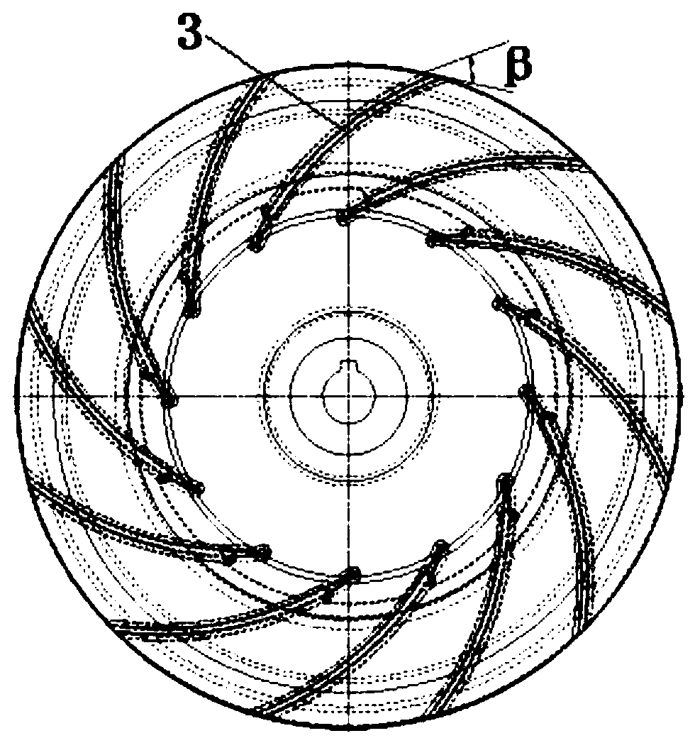
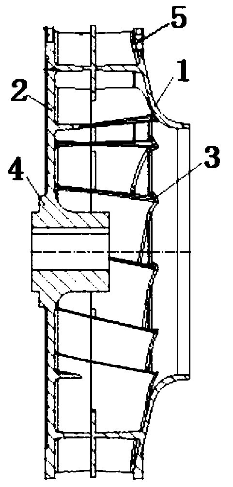
[0031] Such as figure 1 , figure 2 As shown, the impeller includes a wheel cover 1, a wheel disc 2, a blade 3, a shaft disc 4, and a wheel cover 5.

[0032] Wherein, the wheel cover 5, the blade 3, the wheel disc 2, and the wheel cover 1 are all formed into a whole by mold casting.

[0033] Wheel cover 5 can be straight shape, taper, arc.

[0034] The blades 3 can be forward, backward or radial, and NTFB mostly adopts backward blades, such as figure 1 As shown, the blade distribution form in which β<90° is called backward blade.

[0035] The wheel disc 2 and the wheel cover 5 have the same outer diameter, and the outer rings of the wheel disc and the wheel cover are cast with a 3-5mm thick boss edge, which is used for impeller reinforcement and dynamic balancing.

[0036] A method for dynamically balancing a cast aluminum impeller, comprising the following steps:

[0037] Step 1. Use a dynamic balancing machine to perform a dynamic balancing test on the impeller, and det...

Embodiment 2

[0071] In the dynamic balancing method of this embodiment, when the rotating speed of the impeller is lower than 1500r / min, the dynamic balancing method of drilling and tapping the radial edge of the impeller and then injecting lead water can be adopted.

[0072] The scheme of this embodiment can only be used under the condition that the speed of the impeller is lower than 1500r / min. If the speed of the impeller is higher than 1500r / min, the lead weight of the counterweight will be thrown out due to the large centrifugal force.


PUM


Abstract

The invention discloses a dynamic balance method of an impeller, which comprises the steps of 1, conducting a dynamic balance test on the impeller by using a dynamic balance machine, and determining the phase required to be balanced and the required balance mass of the impeller according to the indication of the dynamic balance machine; 2, drilling a plurality of counterweight holes in the phase positions of the radial edges of a wheel disc and a wheel cover of the impeller correspondingly; 3, calculating the weight of lead water counterweight; 4, pouring the lead water counterweight into thecounterweight holes, and plugging the counterweight holes by using aluminum welding; 5, conducting a dynamic balance test on the impeller by using the dynamic balance machine, detecting whether the unbalance amount of the impeller is within a specified range or not, if so, entering the next step, and if not, entering the step 1; and 6, ending the dynamic balance test. According to the dynamic balance method of the impeller, the surface of the impeller is free of uneven balancing weights and holes, aerodynamic noise caused by friction between the balancing weights or the holes and air is greatly reduced, and the generation of howling is avoided.

Description

technical field [0001] The invention belongs to the technical field of centrifugal fans, and in particular relates to a dynamic balancing method of an impeller. Background technique [0002] Centrifugal fans are widely used in ventilation, dust removal and cooling of factories, mines, tunnels, cooling towers, vehicles, ships and buildings; ventilation and drafting of boilers and industrial furnaces; air conditioning equipment and household appliances It is widely used in many fields such as cooling and ventilation in the middle; drying and sorting of grain; wind tunnel wind source and inflation and propulsion of hovercraft. [0003] The dynamic balance of the impeller in the prior art is mainly completed by the counterweight method. One method is to increase the breeding block by means of welding or bolt fastening on the wheel cover and the wheel disc of the impeller; the other method is to use drilling or material removal and other methods. Both methods can control the un...

Claims


Application Information

Patent Timeline
Patent Type & Authority Applications(China)
IPC IPC(8): G01M1/32F04D29/66F04D29/30
CPCF04D29/30F04D29/662G01M1/323
Inventor 肖江东周忠义刘琨
Owner SHANGHAI NUOTE FEIBO COMBUSTION EQUIP CO LTD
Why Eureka
Try Eureka