
A detachable box wheel structure

A box wheel and recessed structure technology, applied in the direction of casters, wheels, luggage, etc., can solve the problems of inability to overcome the thermal expansion and contraction of the axles, the inability to fit, the deformation and damage of the hardware card, etc.

Active Publication Date: 2021-02-23
HANGZHOU GEMA SUITCASES & BAGS
View PDF10 Cites 0 Cited by
  • Summary
  • Abstract
  • Description
  • Claims
  • Application Information

AI Technical Summary

Problems solved by technology

[0003] Existing detachable box wheels are all wheel shafts directly installed in the wheel frame, and the hardware card on the wheel frame is horizontally matched with the wheel shaft to realize the limit and fixation, as documented in the Chinese Patent Publication No. CN207285487U; this installation method only needs to be operated The hardware card can control the disassembly and assembly of the wheel set, which is very convenient, but in fact, with the current technology, it is still impossible to overcome a series of problems such as thermal expansion and contraction of the metal wheel shaft, so that the wheel shaft and the wheel frame can be perfectly matched. That is to say, when the existing wheel shaft is installed in the wheel frame, it cannot fit perfectly with the wheel frame, and there will always be a gap between the top of the wheel shaft and the inner wall of the cover plate of the wheel frame
[0004] Because of the gap between the wheel shaft and the wheel frame, the wheel shaft has room for upward movement in the wheel frame. It should be known that the wheel shaft and the wheel frame are limited by the cooperation of the horizontally arranged hardware cards and the wheel shaft. Landing straight down, when the box wheel is in contact with the ground, the wheel shaft will be forced to generate upward movement potential energy, and the hardware card installed horizontally needs to bear this potential energy, so when the box wheel lands for a certain number of times or the impact generated by the potential energy If the force is large, the hardware card on the wheel frame will be deformed and damaged because it cannot bear the potential energy

Method used


Image

  • A detachable box wheel structure
  • A detachable box wheel structure
  • A detachable box wheel structure

Examples


Embodiment 1

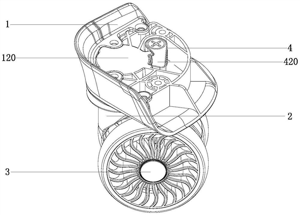
[0033] A detachable box wheel structure, the main body of which is composed of a wheel frame 1, a wheel shaft 2 and a wheel body 3, and one end of the wheel shaft 2 is detachably connected to the wheel frame 1, such as figure 1 shown.

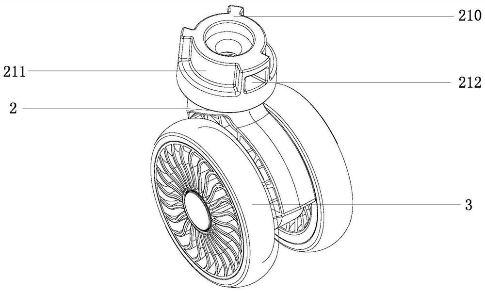
[0034] In this embodiment, an inner wheel frame 210 is provided at one end of the wheel shaft 2 for connecting with the wheel frame 1, such as figure 2 As shown; the inner wheel frame 210 is integrally formed by injection molding, and is sleeved on one end of the wheel shaft 2, and the wheel shaft 2 can rotate horizontally relative to the inner wheel frame 210; the wheel shaft 2 cooperates with the wheel frame 1 through the inner wheel frame 210 connect.

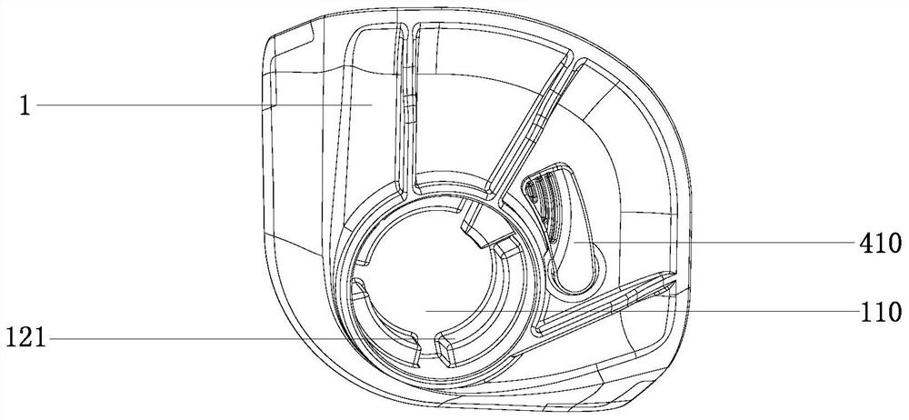
[0035] In this embodiment, the wheel frame 1 is provided with a first through hole 110, and the inner wheel frame 210 can be fitly inserted into the first through hole 110; the upper surface of the wheel frame 1 is provided with a cover plate 120, the cover plate 120 is blocked at its top ...

Embodiment 2

[0043] This embodiment differs from Embodiment 1 in that the outer wall of the inner wheel frame 2 is provided with threads, the first through hole 110 is provided with threads that match the inner wheel frame 210, and the inner wheel frame 210 The detachable connection between the wheel shaft 2 and the wheel frame 1 is realized through threaded connection with the first through hole 110 .


PUM


Abstract

The invention discloses a detachable box wheel structure, which relates to the field of luggage, and its main body is composed of a wheel body, a wheel shaft and a wheel frame. The frame and the wheel frame are connected flexibly. The inner wheel frame overcomes the technical problems caused by the material of the wheel shaft. It has higher precision and can cooperate with the wheel frame without gaps to achieve the purpose of effective fit. The inner wheel frame is fixed on the wheel shaft. The upper is integrated with it, and the wheel shaft is movably connected with the wheel frame through the inner wheel frame, so that the problem of non-fitting of the movable joint between the wheel shaft and the wheel frame is solved.

Description

technical field [0001] The invention relates to the field of cases and bags, in particular to a detachable case wheel structure. Background technique [0002] In the current luggage industry, in order to solve the problem of inconvenient replacement of the suitcase wheel after wear, people have improved the structure of the box wheel and designed a detachable box wheel, that is, the wheel shaft and the wheel frame can be separated. Thereby reach the purpose that the wheel set below the wheel frame can be replaced. [0003] Existing detachable box wheels are all wheel shafts directly installed in the wheel frame, and the hardware card on the wheel frame is horizontally matched with the wheel shaft to realize the limit and fixation, as documented in the Chinese Patent Publication No. CN207285487U; this installation method only needs to be operated The hardware card can control the disassembly and assembly of the wheel set, which is very convenient, but in fact, with the curre...

Claims


Application Information

Patent Timeline
Patent Type & Authority Patents(China)
IPC IPC(8): B60B33/00B60B33/04A45C5/14
CPCB60B33/0002B60B33/0007B60B33/04A45C5/143B60B2200/45B60B33/001
Inventor 吴良林
Owner HANGZHOU GEMA SUITCASES & BAGS
Learn More