Automatic cloth clamping and changing embroidery equipment with left and right cloth rollers
A cloth roller and cloth clamping technology, which is applied in the field of automatic cloth clamping and cloth changing and embroidery equipment, achieves the effect of uniform force, saving operation procedures, and ensuring the straightening state.
- Summary
- Abstract
- Description
- Claims
- Application Information
AI Technical Summary
Problems solved by technology
Method used
Image
Examples
Embodiment 1
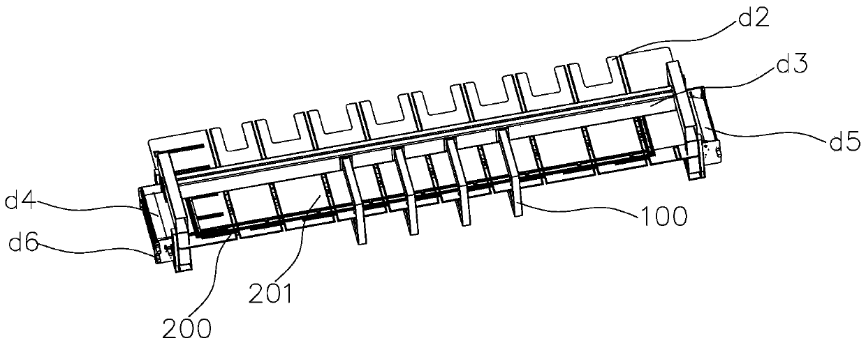
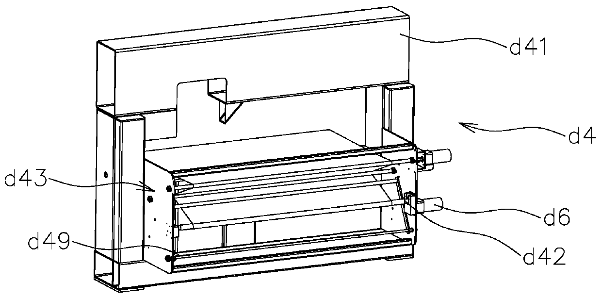
[0040] This embodiment provides an automatic cloth clamping and cloth changing embroidery device with left and right cloth rollers, such as figure 1 As shown, a frame 100 is included. The frame 100 is provided with a platen d2 under the embroidered cloth during the embroidery process, and the cloth clamping air frame 200 is arranged on the platen d2 and connected to the frame 100. The center of the cloth clamping air frame 200 is the embroidery area 201. The mounting beam d3 is located directly above the table d2 and is connected to the frame 100. The two ends of the frame 100 are respectively provided with first cloth roller assemblies for winding embroidery cloth d4 and the second cloth roller assembly d5, the first cloth roller assembly d4 and / or the second cloth roller assembly d5 is also connected with a driving assembly d6, the driving assembly d6 can drive the first cloth roller assembly d4 or the second The cloth roller assembly d5 rotates.
[0041] In the present inventi...
Embodiment 2
[0073] This embodiment provides a cloth clamping method implemented by the automatic cloth clamping and cloth changing embroidery device with cloth rollers on the left and right in embodiment 1. Figure 1-15 As shown, the specific steps are as follows:
[0074] (1) Sewing ribs on the two opposite edges of the embroidered cloth;
[0075] (2) Start the lifting driver 24 on the left side (feeding end side) of the cloth clamping air frame 200 to keep the cloth presser 25 away from the cloth sill 22 so that the head end of the embroidery cloth can pass through, and then start the lifting driver 24 again to make The cloth pressing strip 25 is close to the cloth sill 22 to press the end of the embroidered cloth; and the raised edge of the embroidered cloth edge is inserted into the corresponding side cloth clamping area from the opening of the side cloth clamping area;
[0076] (3) Continue to pull the head end of the embroidered cloth to the right side of the cloth clamping air frame 200 ...
Embodiment 3
[0079] This embodiment provides a cloth clamping method implemented by the automatic cloth clamping and cloth changing embroidery device with cloth rollers on the left and right in embodiment 1. Figure 1-15 As shown, the specific steps are as follows:
[0080] (Ⅰ) Sewing ribs on the two opposite edges of the embroidered cloth, and wind the embroidered cloth with ribs on the reel shaft d42 to obtain an embroidered cloth roll;
[0081] (Ⅱ) Install the embroidered cloth roll with cloth winding shaft d42 on the embroidery machine, so that the cloth winding shaft d42 is linked with the output shaft of the drive assembly d6;
[0082] (Ⅲ) Same as steps (1)-(3) in Example 2;
[0083] (IV) Pull the head end of the embroidered cloth from the discharge end of the cloth clamping air frame 200, start the driving assembly d6 on the other side, and wind the head end of the embroidered cloth onto the cloth winding shaft d42 on the other side; After the embroidery roll is finished embroidering, take...
PUM
 Abstract
Description
Claims
Application Information
 - R&D
- Intellectual Property
- Life Sciences
- Materials
- Tech Scout
- Unparalleled Data Quality
- Higher Quality Content
- 60% Fewer Hallucinations
Browse by: Latest US Patents, China's latest patents, Technical Efficacy Thesaurus, Application Domain, Technology Topic, Popular Technical Reports.
© 2025 PatSnap. All rights reserved.Legal|Privacy policy|Modern Slavery Act Transparency Statement|Sitemap|About US| Contact US: help@patsnap.com


