Operation structure for ground potential live-line lapping operation
A technology of ground potential and positioning board, which is applied in the direction of equipment for connecting/terminating cables, etc., and can solve problems such as large-scale power outages
- Summary
- Abstract
- Description
- Claims
- Application Information
AI Technical Summary
Problems solved by technology
Method used
Image

Examples
Embodiment 1
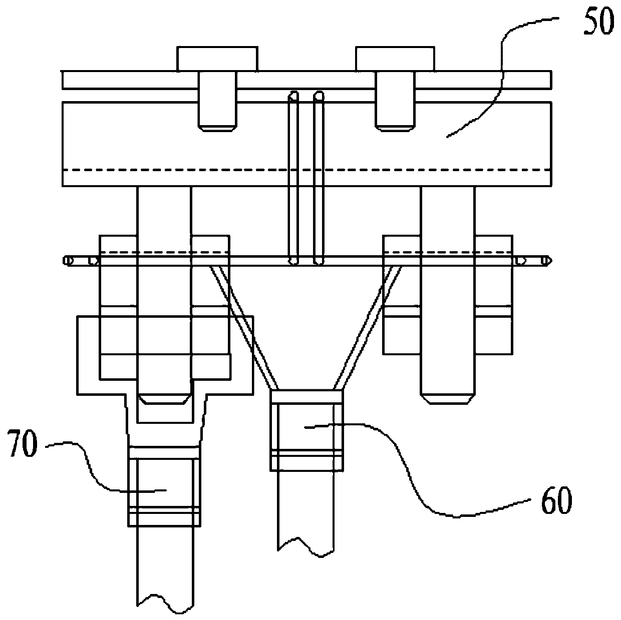
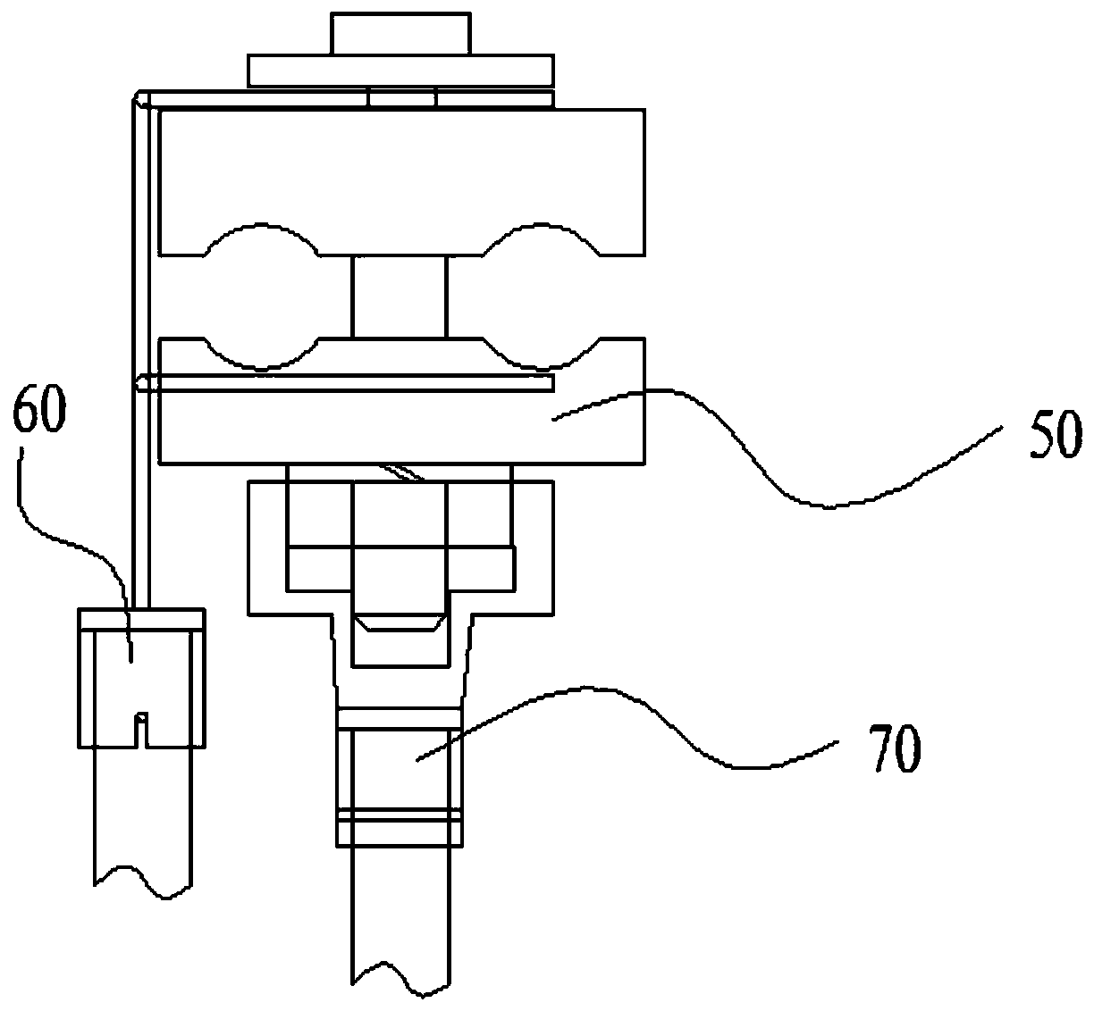
[0027] Embodiment 1: as attached Figure 1-11 As shown, an operating structure for ground potential live fire-taking operation, it includes a wire clamp assembly 50, a support rod assembly 60 and a sleeve assembly 70, the wire clamp assembly 50 is supported on the support rod assembly 60, and the sleeve The assembly 70 is located below the wire clamp assembly 50. The wire clamp assembly 50 includes an upper splint 7 and a lower splint 6. Both the upper splint 7 and the lower splint 6 have a square structure, and two studs 5 are fixedly connected below the upper splint 7. , the lower splint 6 is set on the stud 5 and fixed by the washer 3 and the nut 4. On the opposite surface of the upper splint 7 and the lower splint 6, there are up and down symmetrical arc grooves 8, and the wires to be connected are located at In groove 8. Let the pre-fired equipment reserve a connection line, and fix the line reserved by the fire-fired equipment on the wire clip by selecting a suitable wi...
Embodiment 2
[0039] Embodiment 2: as attached Figure 1-11 As shown, an operating structure for ground potential live fire-taking operation, it includes a wire clamp assembly 50, a support rod assembly 60 and a sleeve assembly 70, the wire clamp assembly 50 is supported on the support rod assembly 60, and the sleeve The assembly 70 is located below the wire clamp assembly 50. The wire clamp assembly 50 includes an upper splint 7 and a lower splint 6. Both the upper splint 7 and the lower splint 6 have a square structure, and three studs 5 are fixedly connected below the upper splint 7. The lower splint 6 is set on the stud 5 and fixed by the gasket 3 and the nut 4. On the opposite surface of the upper splint 7 and the lower splint 6, there are up and down symmetrical arc-shaped grooves 8, and the wires to be connected are located in the grooves. In slot 8. Let the pre-fired equipment reserve a connection line, and fix the line reserved by the fire-fired equipment on the wire clip by selec...
Embodiment 3
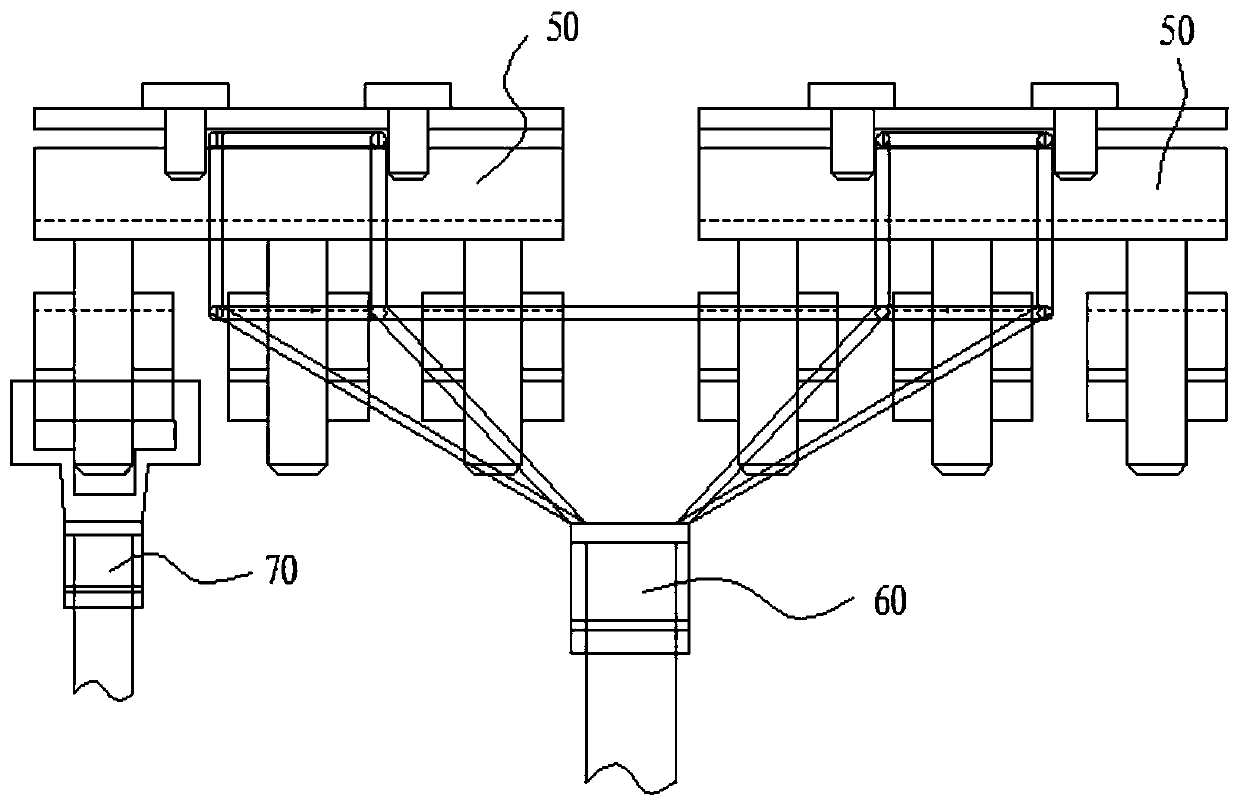
[0052] Embodiment 3: as attached Figure 2-11 As shown, an operating structure for ground potential electrification work, it includes a clamp assembly 50, a support rod assembly 60 and a sleeve assembly 70, the two clamp assemblies 50 are supported on the support rod assembly 60, The sleeve assembly 70 is located below the wire clamp assembly 50. The wire clamp assembly 50 includes an upper splint 7 and a lower splint 6. Both the upper splint 7 and the lower splint 6 have a square structure, and three studs are fixedly connected to the bottom of the upper splint 7. 5. The lower splint 6 is set on the stud 5 and fixed by the gasket 3 and the nut 4. On the opposite surface of the upper splint 7 and the lower splint 6, there are up and down symmetrical arc grooves 8, and the wires to be connected Located in groove 8. Let the pre-fired equipment reserve a connection line, and fix the line reserved by the fire-fired equipment on the wire clip by selecting a suitable wire clip, and...
PUM
 Abstract
Description
Claims
Application Information
 - R&D
- Intellectual Property
- Life Sciences
- Materials
- Tech Scout
- Unparalleled Data Quality
- Higher Quality Content
- 60% Fewer Hallucinations
Browse by: Latest US Patents, China's latest patents, Technical Efficacy Thesaurus, Application Domain, Technology Topic, Popular Technical Reports.
© 2025 PatSnap. All rights reserved.Legal|Privacy policy|Modern Slavery Act Transparency Statement|Sitemap|About US| Contact US: help@patsnap.com