A rail micro-tillage system for terraced tea gardens
A technology for tea gardens and tracks, applied in the field of micro-tillage systems, can solve the problems of irregular use and handling of micro-tillers, difficult to standardize operation procedures, time-consuming and labor-intensive cross-stalk operation, etc., to improve work quality, simple and reasonable structure, Small footprint effect
- Summary
- Abstract
- Description
- Claims
- Application Information
AI Technical Summary
Problems solved by technology
Method used
Image
Examples
specific Embodiment approach 1
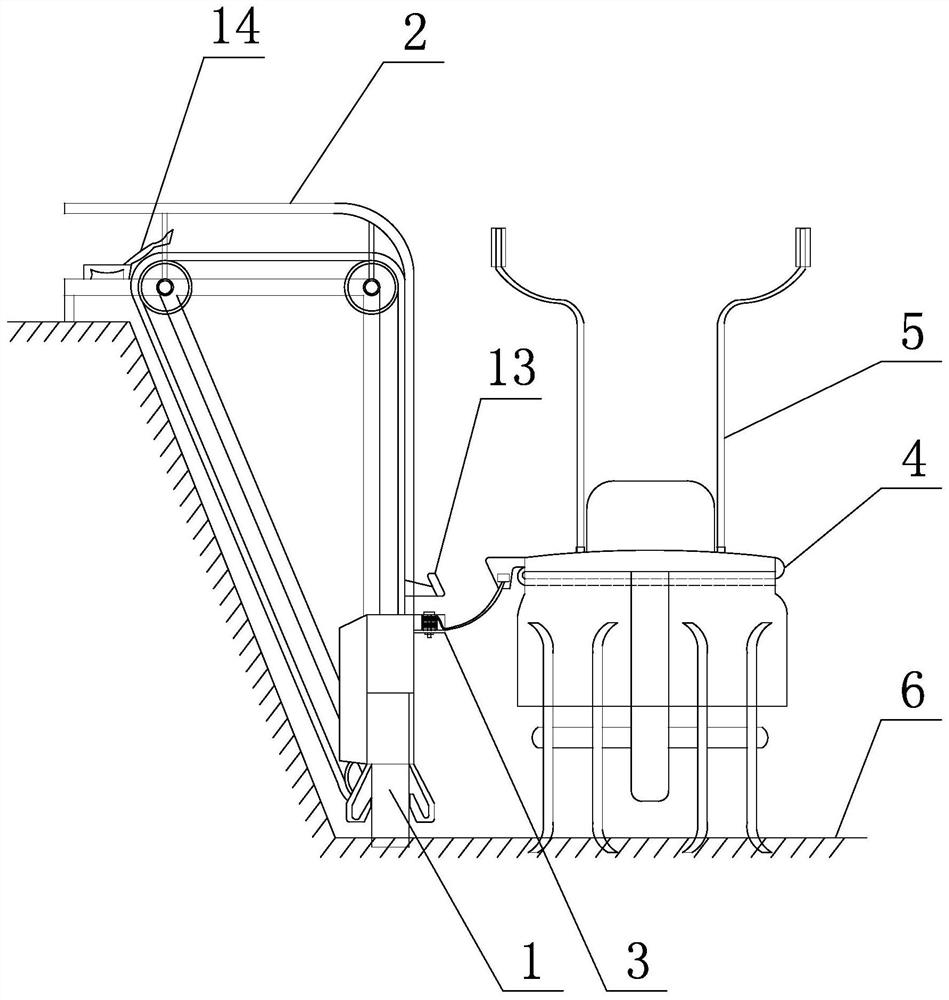
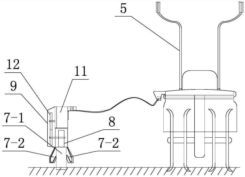
[0037] Specific implementation mode one: combine Figure 1 to Figure 15 Describe this embodiment. This embodiment includes a track micro-tillage system for terraced tea gardens, including a horizontal limit assembly 1, a transmission assembly 2 for field ridges, a limit connector 3, a binding connector 4 and a tiller 5. The horizontal limiting assembly 1 is arranged on the field surface of the terraced field 6 along the length direction of the terraced field 6. The horizontal limiting assembly 1 includes a horizontal monorail 7, a moving wheel 8 and a casing 9. The casing 9 is arranged on the horizontal monorail 7. The casing 9 is provided with a moving wheel 8, the rolling surface of the moving wheel 8 is matched with the top of the horizontal monorail 7, and the limited connector 3 is arranged on the outer casing 9, and the binding connector 4 is detachably connected to the tiller 5, and the outer casing 9 is detachably connected to the tiller 5 through the limit connector 3...
specific Embodiment approach 2
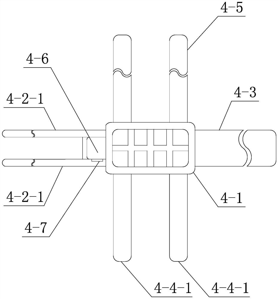
[0038]Specific Embodiment 2: This embodiment is a further limitation of Specific Embodiment 1. The binding connector 4 includes a flexible weight plate 4-1, a first transverse connecting bar 4-2, a second transverse connecting bar 4-3, a second transverse connecting bar 4-3, A longitudinal connecting bar 4-4, a second longitudinal connecting bar 4-5, a block-shaped connecting edge 4-6, a flexible weight plate 4-1 is a rectangular piece, and the first transverse connecting bar 4-2 and the second transverse connecting bar The bars 4-3 are respectively arranged at both ends of the flexible weight plate 4-1, the first transverse connecting bar 4-2 and the second transverse connecting bar 4-3 are detachably connected, the first longitudinal connecting bar 4-4 and the The second longitudinal connection bar 4-5 is respectively arranged on both sides of the flexible counterweight plate 4-1, the first longitudinal connection bar 4-4 and the second longitudinal connection bar 4-5 are det...
specific Embodiment approach 3
[0043] Specific embodiment three: this embodiment is a further limitation of specific embodiment two, the first horizontal connecting bar 4-2 includes two single strips 4-2-1, two single strips 4-2-1 are arranged side by side, and the single strip 4-2 - the width of 1 is less than a quarter of the width of the second transverse connecting strip 4-3; the first longitudinal connecting strip 4-4 includes two adhesive strips 4-4-1, two adhesive strips 4-4-1 They are arranged side by side with a heat dissipation gap formed between them, which is similar to the structural arrangement of the second longitudinal connecting bars 4-5.
PUM
 Abstract
Description
Claims
Application Information
 - R&D
- Intellectual Property
- Life Sciences
- Materials
- Tech Scout
- Unparalleled Data Quality
- Higher Quality Content
- 60% Fewer Hallucinations
Browse by: Latest US Patents, China's latest patents, Technical Efficacy Thesaurus, Application Domain, Technology Topic, Popular Technical Reports.
© 2025 PatSnap. All rights reserved.Legal|Privacy policy|Modern Slavery Act Transparency Statement|Sitemap|About US| Contact US: help@patsnap.com


