
Display mounting assembly in vehicle

A vehicle interior and display technology, applied to vehicle components, transportation and packaging, etc., can solve problems such as unfavorable disposal measures, inability to adjust angles, and high potential safety hazards, so as to reduce observation obstacles and visual fatigue, improve driving safety, and assemble The effect of easy disassembly

Pending Publication Date: 2019-12-27
青岛即东汽车零部件有限公司
View PDF0 Cites 2 Cited by
  • Summary
  • Abstract
  • Description
  • Claims
  • Application Information

AI Technical Summary

Problems solved by technology

The installation position and structure of such existing vehicle internal displays mainly have the following disadvantages: 1. The display is placed on the main control panel, which is not easy to disassemble and replace, and it is necessary to lower the head when observing, which leads to high driving risks. It needs to be completely fixed and the angle cannot be adjusted; 2. Other installation positions directly block part of the driver's line of sight, leaving a small blind area in the direct field of vision, which affects driving safety; 3. When observing, the driver's head needs to be specially twisted Long-term observation will still easily lead to discomfort and driving fatigue; 4. The angle of the installation position causes the driver to observe in an uncomfortable range of rotation angles. The actual field of vision on both sides of the car is limited and has not reached Ideal observation effect, but the potential safety hazard is still high; 5. The installation of the monitor has not realized the rigid connection with the frame of the car body, so the vibration of the monitor and the frame of the car body is not synchronized, and the vibration between the monitor and the driver will still be misaligned and cause A certain observation obstacle is formed, and the visual inspection effect is not good. Under this condition, the driver's visual recognition time is longer, which is not conducive to taking timely disposal measures before a traffic accident occurs, and the safety hazard is relatively large.

Method used


Image

  • Display mounting assembly in vehicle
  • Display mounting assembly in vehicle
  • Display mounting assembly in vehicle

Examples


Embodiment 1

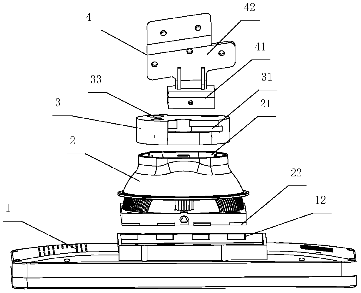
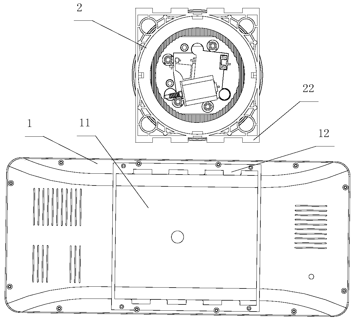
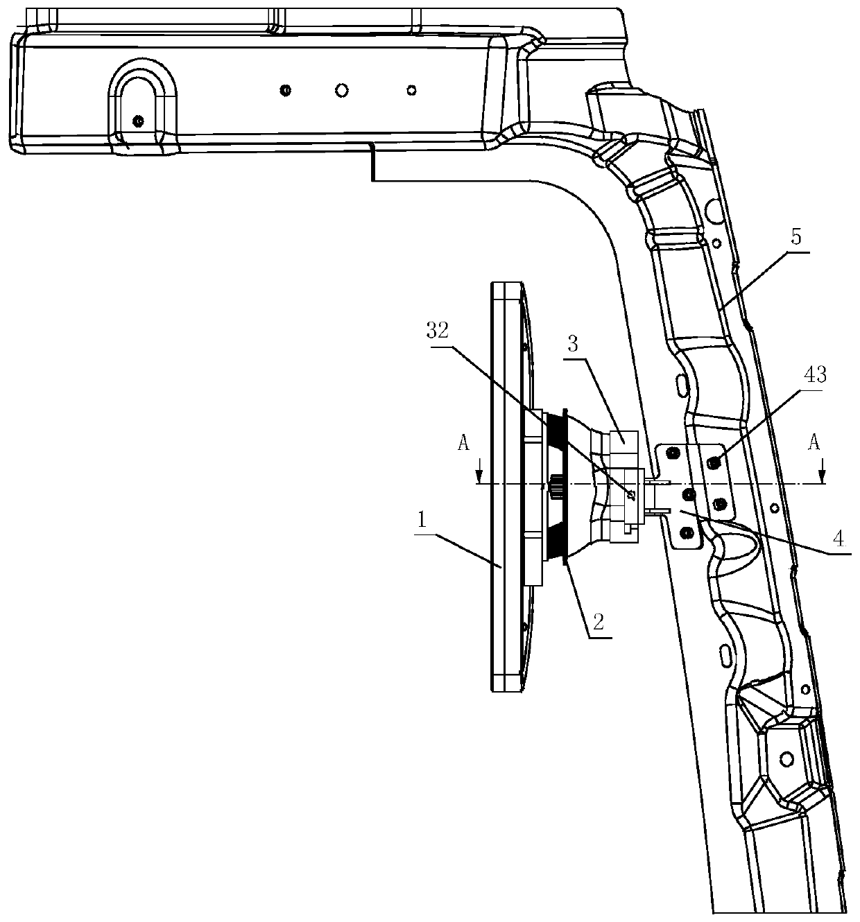
[0030] Example 1, such as Figure 1 to Figure 4 As shown, the display installation assembly provided by the present application can be used to install two left and right displays 1 inside the vehicle, so as to respectively display the environmental conditions on both sides outside the vehicle correspondingly.

[0031] Specifically, the display 1 is installed at the A-pillar of the vehicle body frame, and the installation assembly includes a connecting block 3 for connecting the driver 2, and a connecting bracket 4 installed on the sheet metal part 5 of the A-pillar;

[0032] The driver 2 has a vertical guide post 21 with a threaded hole, and the connecting block 3 has a vertical through hole 33 , and bolts pass through the through hole 33 and the guide post 21 in turn for fastening connection.

[0033] A rectangular slot 11 is opened on the back of the display 1 , and two rows of saw-toothed stoppers 12 are arranged in the rectangular slot 11 , and a saw-toothed baffle 22 is p...


PUM


Abstract

The invention discloses a display mounting assembly in a vehicle. Aiming at the mounting problem of the display in the vehicle, a mounting solution at an A column of a vehicle body frame is provided,so that a driver observes the display in a comfortable mode conforming to ergonomics, the fatigue caused by the long-time frequent observation is effectively relieved, the observation efficiency and accuracy are improved, and the driving safety is improved. The mounting assembly comprises a connecting block used for being connected with a driver and a connecting support mounted on an A column sheet metal part, wherein the connecting support is provided with a front-end clamping jaw and a connecting plate which are welded into an integrated structure, the front-end clamping jaw is inserted intothe clamping groove of the connecting block, the front-end clamping jaw and the connecting block are fastened through screws, and the front end clamping jaw is of a U-shaped structure.

Description

technical field [0001] The invention relates to a structural assembly for installing a display inside a vehicle, specifically realizing the installation structure and method at the A-pillar of the vehicle body frame, and belongs to the field of vehicle component design. Background technique [0002] At present, in the process of driving a vehicle, the driver usually observes the road conditions and the two sides of the vehicle's exterior mainly based on the rearview mirror installed outside the vehicle. Continue to observe continuously to improve the range and accuracy of visual inspection. [0003] In order to improve the accuracy and timeliness of observation of the environment outside the vehicle and reduce driving fatigue caused by repeated observations, existing vehicles will install cameras outside the vehicle, and at the same time install cameras on the main control panel, windshield or driving table in the vehicle. The design of the display is added above. The inst...

Claims


Application Information

Patent Timeline
IPC IPC(8): B60R11/02
CPCB60R11/0229B60R2011/0022B60R2011/008
Inventor 李贵林王宏伟蒋涛赵洪伟吴润祥金显仲
Owner 青岛即东汽车零部件有限公司
Learn More