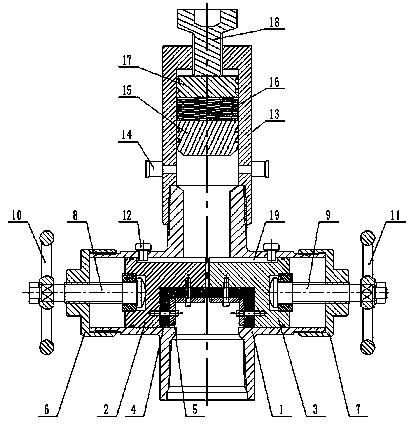
Controllable well plugging tool

A controllable well sealing technology, applied in the direction of sealing/isolation, wellbore/well parts, wellbore/well valve device, etc., can solve the problems of casualties, property loss, fire and explosion, etc., and achieve improved sealing Speed ​​and tightness, improve the sealing effect, optimize the effect of structural design

Pending Publication Date: 2019-12-27
东营市三和石油装备有限公司
View PDF0 Cites 0 Cited by
  • Summary
  • Abstract
  • Description
  • Claims
  • Application Information

AI Technical Summary

Problems solved by technology

[0002] In the late stage of oilfield development, some oil and water wells need to be closed due to various reasons. At present, the commonly used method is to seal and weld the short joints of the casing with steel plates after removing the ground equipment and wellheads. However, the oil wells may still be reused. The oil and gas in the wells The wellbore is not completely sealed, and there is still a large amount of oil, water and natural gas in the wellbore. When production needs to be resumed, the pressure in the well cannot be measured because the short joint is welded and sealed, and the gas content in the well cannot be known. If it is cut forcibly, the high-pressure gas in the well will be ejected instantly, and even fire and explosion will be caused, causing property loss or casualties

Method used


Image

  • Controllable well plugging tool

Examples


Embodiment Construction

[0017] The following will clearly and completely describe the technical solutions in the embodiments of the present invention with reference to the accompanying drawings in the embodiments of the present invention. Obviously, the described embodiments are only some, not all, embodiments of the present invention. Based on the embodiments of the present invention, all other embodiments obtained by persons of ordinary skill in the art without making creative efforts belong to the protection scope of the present invention.

[0018] In the description of the present invention, it should be noted that the terms "upper", "lower", "inner", "outer", "front end", "rear end", "both ends", "one end", "another end" The orientation or positional relationship indicated by etc. is based on the orientation or positional relationship shown in the drawings, and is only for the convenience of describing the present invention and simplifying the description, rather than indicating or implying that ...


PUM


Abstract

The invention discloses a controllable well plugging tool. The controllable well plugging tool comprises a body, a core valve assembly and a pressure relief device, wherein the body is of a cross-shaped four-way structure; a first valve cap and a second valve cap are arranged at the left end and right end of the body; a first valve rod and a second valve rod are respectively arranged in the firstvalve cap and the second valve cap; the core valve assembly is arranged inside the body and is formed by jointing a first core body and a second core body; one end of the first valve rod is fixedly connected to the first core body through a roller bearing; the other end of the first valve rod penetrates the first valve cap, and a first hand wheel is arranged at the extension part of the outer endof the first valve rod; one end of the second valve rod is fixedly connected to the second core body through a roller bearing; the other end of the second valve rod penetrates the second valve cap, and a second hand wheel is arranged at the extension part of the outer end of the second valve rod; and the pressure relief device is arranged at an opening of the upper end of the body. Compared with the prior art, the controllable well plugging tool has the beneficial effects that the controllable well plugging tool has a simple and reliable structure and a good sealing property; meanwhile the controllable well plugging tool has an adjustable pressure relief function so as to ensure the safety of operation.

Description

technical field [0001] The invention relates to the technical field of oil collection, in particular to a controllable well sealing tool. Background technique [0002] In the late stage of oilfield development, some oil and water wells need to be closed due to various reasons. At present, the commonly used method is to seal and weld the short joints of the casing with steel plates after removing the ground equipment and wellheads. However, the oil wells may still be reused. The oil and gas in the wells The wellbore is not completely blocked, and there is still a large amount of oil, water and natural gas in the wellbore. When production needs to be resumed, the pressure in the well cannot be measured because the short joint is welded and sealed, and the gas content in the well cannot be known. If it is forcibly cut open, the high-pressure gas in the well will spray out instantly, and even cause a fire and explosion, causing property damage or casualties. Contents of the in...

Claims


Application Information

Patent Timeline
Patent Type & Authority Applications(China)
IPC IPC(8): E21B33/03E21B34/02E21B34/16
CPCE21B33/03E21B34/02E21B34/16
Inventor 王树杰
Owner 东营市三和石油装备有限公司
Why Eureka
Try Eureka