Charge pump-based wireless power receiver

A wireless power and receiver technology, applied to battery circuit devices, high-efficiency power electronic conversion, electrical components, etc., to achieve high efficiency and small footprint

Inactive Publication Date: 2019-12-27
MAPS
View PDF0 Cites 4 Cited by
  • Summary
  • Abstract
  • Description
  • Claims
  • Application Information

AI Technical Summary

Problems solved by technology

Drive loss is the loss that occurs in driving the switch in the rectifier, and conduction loss is the loss that occurs in the switch

Method used


Image

  • Charge pump-based wireless power receiver
  • Charge pump-based wireless power receiver
  • Charge pump-based wireless power receiver

Examples


Embodiment Construction

[0019] The advantages and features of the present invention and the manner of achieving them will become apparent with reference to the embodiments described in detail below and the accompanying drawings. However, this invention may be embodied in many different forms and should not be construed as limited to the embodiments set forth herein, which are provided so that this disclosure will be thorough and complete, and will fully convey to those skilled in the art The scope of the invention is conveyed, and the invention is limited only by the scope of the appended claims. Throughout this disclosure, like reference numerals refer to like parts.

[0020] In the following description of the embodiments of the present invention, if it is determined that a detailed description of a related known function or configuration unnecessarily obscures the gist of the present invention, its detailed description will be omitted herein. Terms described below are defined in consideration of ...


PUM


Abstract

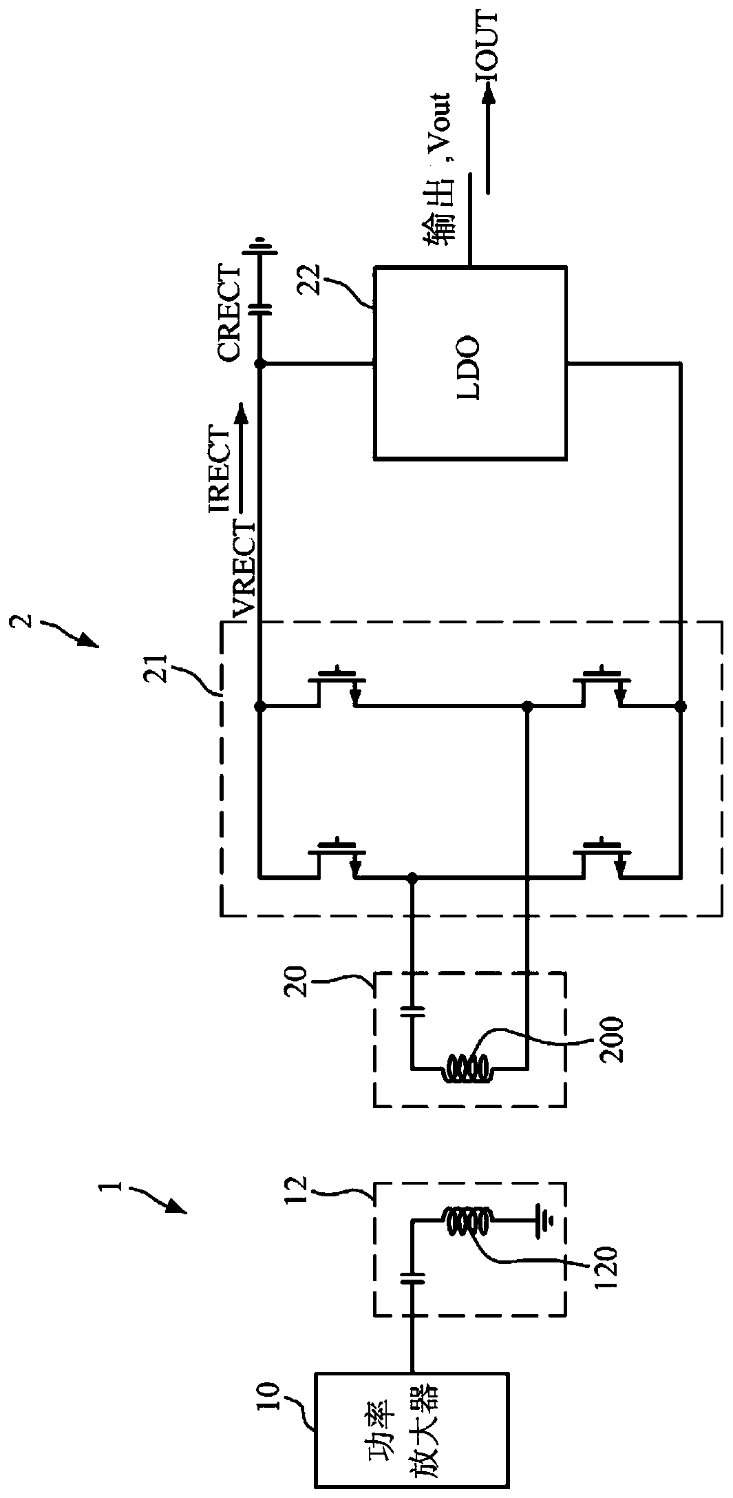
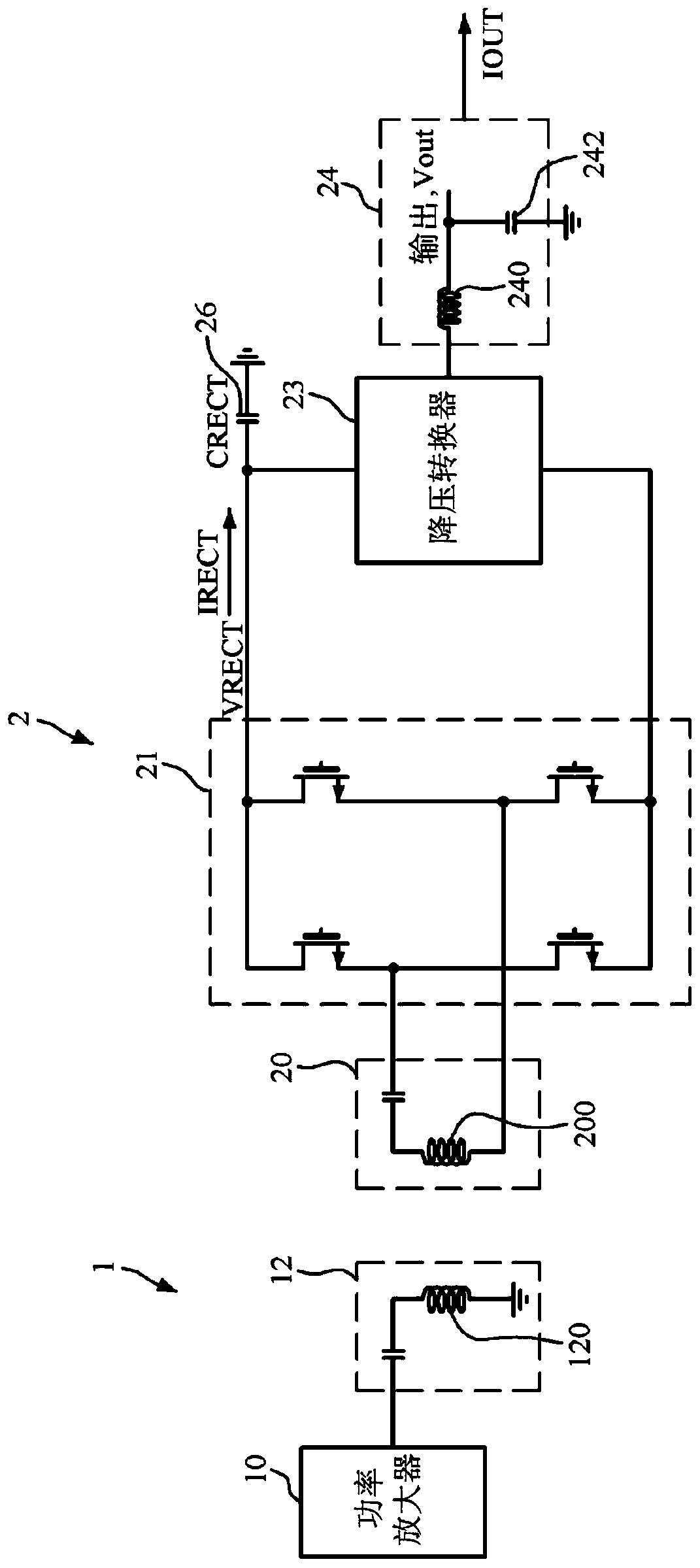
A wireless power receiver according to an embodiment includes: a resonator for receiving wireless power; a rectifier for rectifying the wireless power received from the resonator into a DC waveform; and a charge pump for receiving input of the rectified power from the rectifier, and reduces loss in the rectifier following the attenuation and output of the voltage of the input power.

Description

technical field [0001] The present invention relates to a wireless power transmission system, and more particularly, to a direct current (DC)-DC voltage converter for reducing loss of a rectifier and a wireless power receiving device including the same. Background technique [0002] A general direct current (DC)-DC voltage converter used in a wireless power transmission system receives a DC voltage and steps up or down the received DC voltage to a regulated voltage required at the output of the DC-DC voltage converter. In the rectifier for outputting the rectified DC voltage to the DC-DC voltage converter, driving loss and conduction loss occur. The driving loss is the loss generated by driving the switch in the rectifier, and the conduction loss is the loss generated in the switch. Conduction losses are proportional to the square of the current flowing in the switch and are proportional to the resistance of the switch. In a wireless power receiver, a rectifier is a very i...

Claims


Application Information

Patent Timeline
Patent Type & Authority Applications(China)
IPC IPC(8): H02J50/00H02M3/07
CPCH02J7/02H02M3/07H02M3/155H02M3/33592H02J50/10H02J2207/20H02M1/0045H02M1/007Y02B40/00Y02B70/10H02M3/073H02J50/12H02J50/80
Inventor 黄锺泰郑晖龙申铉翊李焌
Owner MAPS
Why Eureka
Try Eureka