Method and apparatus for inductively transferring ac power between a charging unit and a vehicle

a charging unit and inductive transfer technology, applied in the direction of charging stations, electric vehicle charging technology, transportation and packaging, etc., can solve the problems of inability to achieve the optimal alignment of the vehicle with the charging station, insufficient compensation of inefficiency, etc., and achieve the effect of maximizing the power transfer efficiency

Inactive Publication Date: 2013-02-07
PLUGLESS POWER INC
View PDF5 Cites 62 Cited by
  • Summary
  • Abstract
  • Description
  • Claims
  • Application Information

AI Technical Summary

Benefits of technology

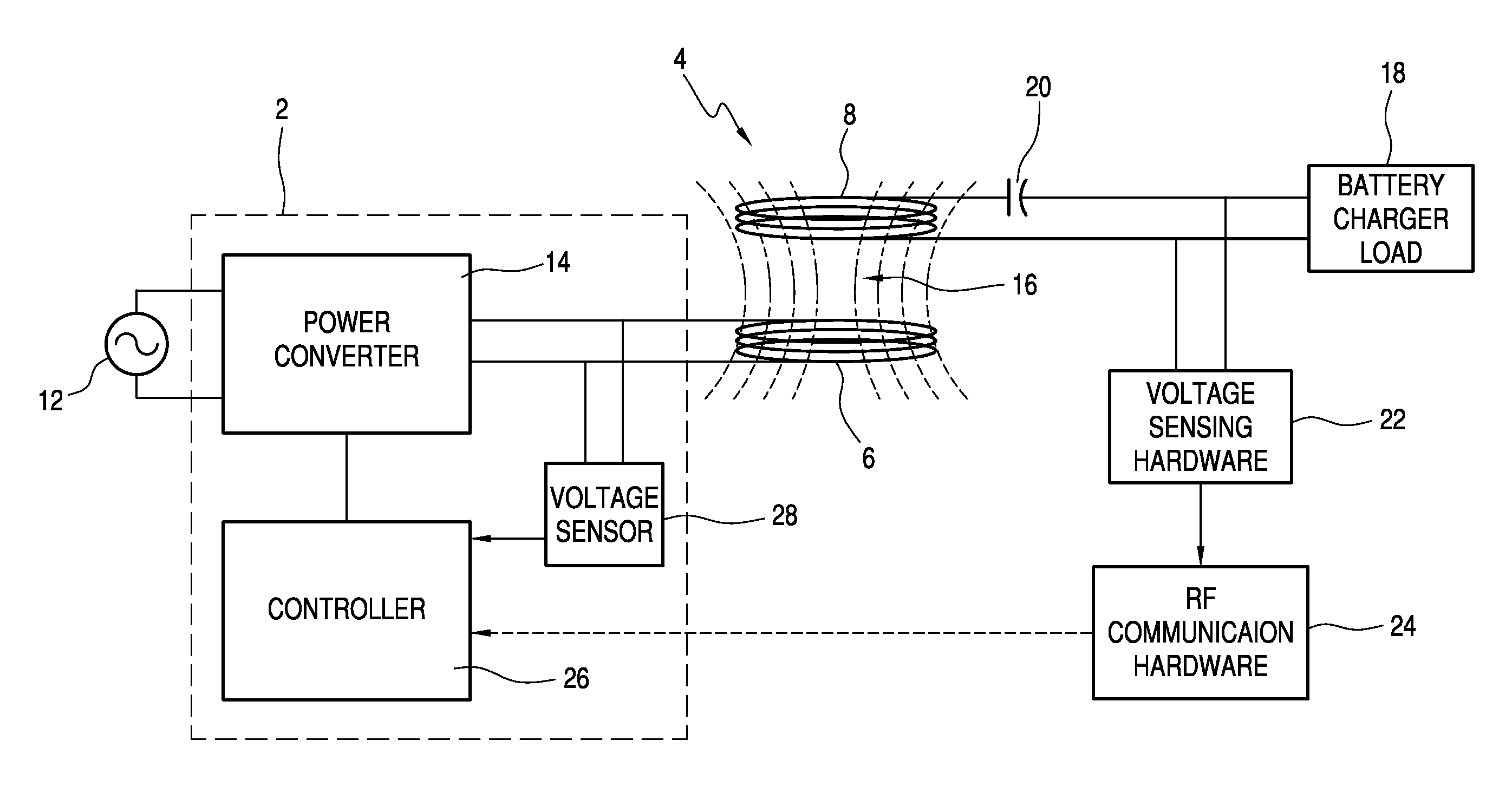
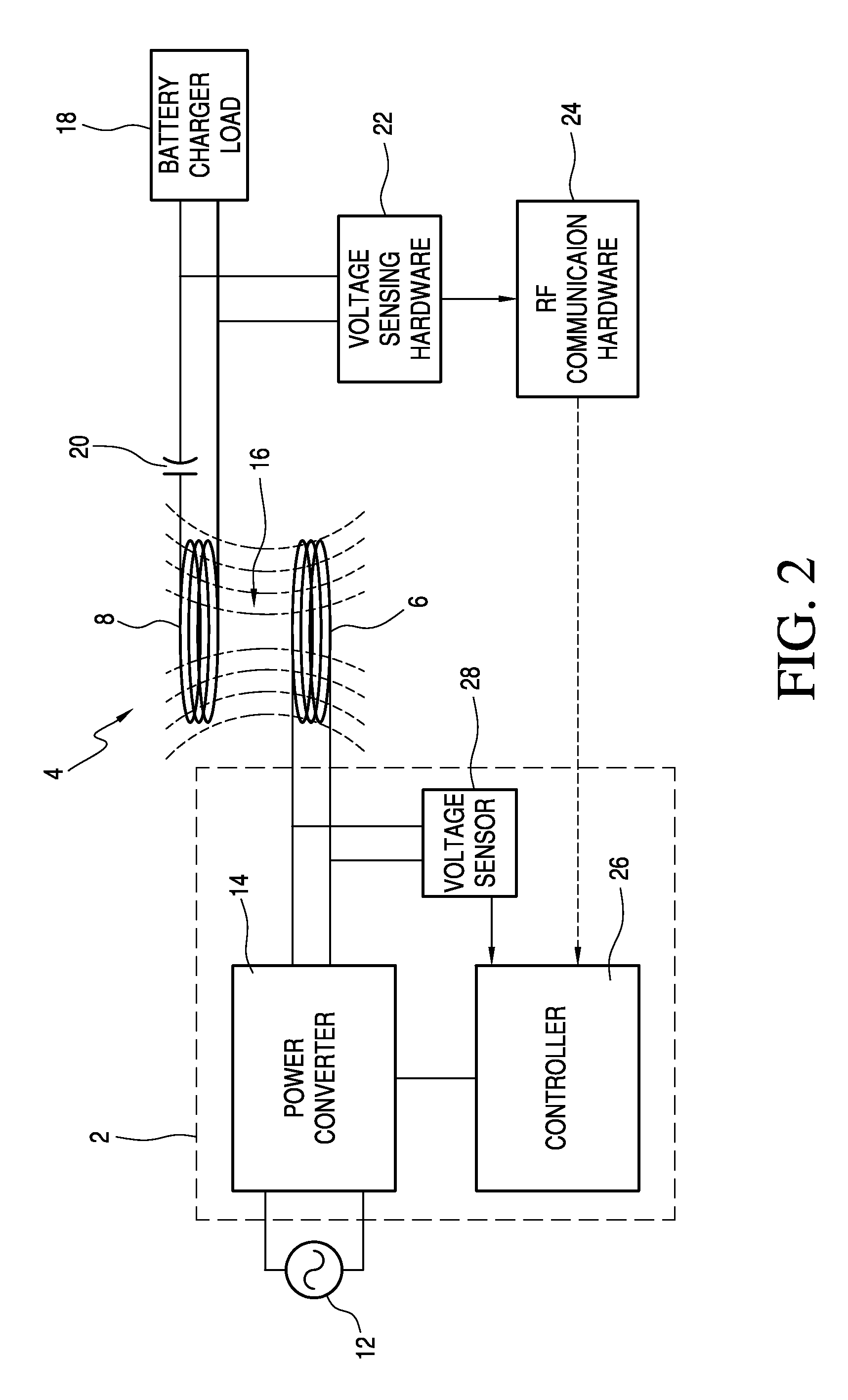
[0009]The power source includes a sinusoidal voltage source and a power converter connected between the sinusoidal voltage source and the transformer primary coil. The power converter converts the sinusoidal voltage from the power source to a variable output which is delivered to the primary coil. The controller establishes a resonant frequency for the charging system to accommodate for variations in leakage reactance and series capacitance, thereby to maximize the efficiency of power transfer from the stationary primary coil to the vehicle secondary coil.

Problems solved by technology

While the prior devices operate satisfactorily, they do not adequately compensate for inefficiency resulting from misalignment of the secondary and primary vehicles.
However, because the secondary coil is mounted on the vehicle, optimum alignment of the vehicle with a charging station is not always attained.

Method used


Image

  • Method and apparatus for inductively transferring ac power between a charging unit and a vehicle
  • Method and apparatus for inductively transferring ac power between a charging unit and a vehicle
  • Method and apparatus for inductively transferring ac power between a charging unit and a vehicle

Examples


Embodiment Construction

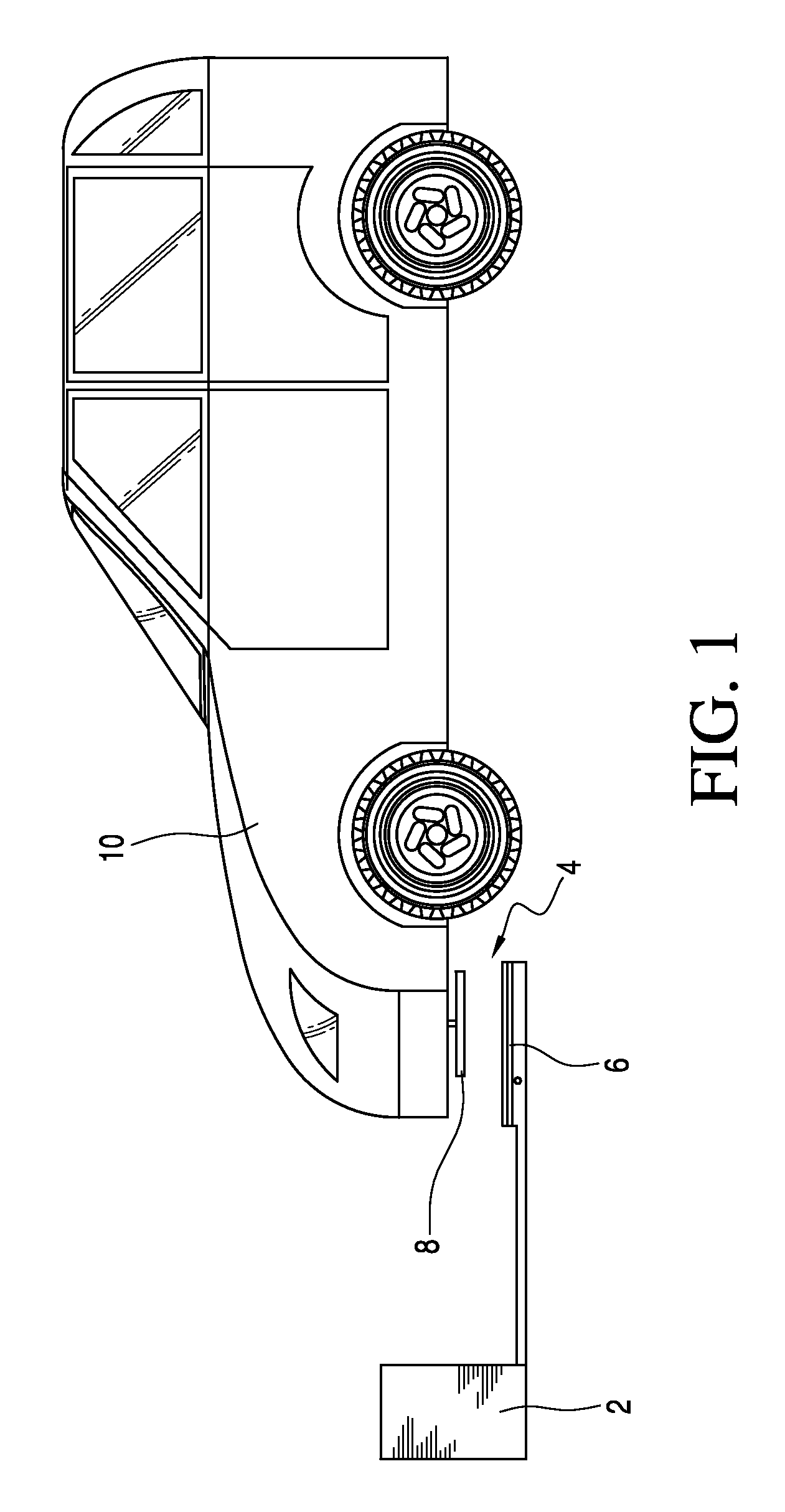
[0013]Referring first to FIG. 1, the inductive charging system according to the invention will be described. The system includes a charging station 2 and transformer 4. The transformer includes a stationary primary coil 6 which is preferably mounted on the ground such as the floor of a garage. The primary coil is connected with the charging station. The transformer further includes a secondary coil 8 which is mounted on a vehicle 10. The secondary coil is mounted at a location on the vehicle so that the vehicle can be positioned adjacent to the charging station with the secondary coil above the primary coil as shown. Preferably, the coils are arranged with their axes in alignment for maximum energy transfer. However, because axial alignment is imprecise, the inductive charging system according to the invention is designed to adjust the charging station to maximize energy transfer.

[0014]The inductive charging system according to the invention will be described in greater detail with ...


PUM


Abstract

An inductive charging system for vehicle battery chargers includes a transformer having a stationary primary coil and a secondary coil mounted on the vehicle. The primary coil is mounted in a charging station and has a power source connected therewith. When the vehicle is parked adjacent to the charging station, the secondary coil on the vehicle is proximate to the primary coil in the station. The power source is activated to deliver current to the primary coil which generates a magnetic field to induce a voltage in the secondary coil. A controller is connected with the power source to adjust the voltage delivered to the primary coil. A feedback loop between the secondary coil and the controller delivers a secondary voltage signal to the controller which continuously adjusts the power source in order to maintain the secondary output voltage at a predetermined value.

Description

BACKGROUND OF THE INVENTION[0001]Electric vehicle energy storage systems are normally recharged using direct contact conductors between an alternating current (AC) source such as is found in most homes in the form or electrical outlets; nominally 120 or 240 VAC. A well known example of a direct contact conductor is a two or three pronged plug normally found with any electrical device. Manually plugging a two or three pronged plug from a charging device to the electric automobile requires that conductors carrying potentially lethal voltages be handled. In addition, the conductors may be exposed, tampered with, or damaged, or otherwise present hazards to the operator or other naïve subjects in the vicinity of the charging vehicle. Although most household current is about 120 VAC single phase, in order to recharge electric vehicle batteries in a reasonable amount of time (two-four hours), it is anticipated that a connection to a 240 VAC source would be required because of the size and ...

Claims


Application Information

Patent Timeline
Patent Type & Authority Applications(United States)
IPC IPC(8): H02J7/00
CPCH02J7/0027H02J7/025B60L11/182Y02T90/14Y02T90/122Y02T10/7005Y02T10/7072B60L53/126H02J50/10H02J50/80Y02T10/70H02J50/12H02J50/70Y02T90/12
Inventor RAEDY, STEVEN
Owner PLUGLESS POWER INC
Why Eureka
Try Eureka