A low re number uniform air supply device

An air supply device and uniform technology, applied in the field of ventilation, can solve problems such as poor ventilation effect in building spaces

Active Publication Date: 2021-07-06
XI'AN UNIVERSITY OF ARCHITECTURE AND TECHNOLOGY
View PDF7 Cites 0 Cited by
  • Summary
  • Abstract
  • Description
  • Claims
  • Application Information

AI Technical Summary

Problems solved by technology

[0004] Aiming at the defects and deficiencies in the prior art, the purpose of the present invention is to provide ...

Method used


Image

  • A low re number uniform air supply device
  • A low re number uniform air supply device
  • A low re number uniform air supply device

Examples


Embodiment 1

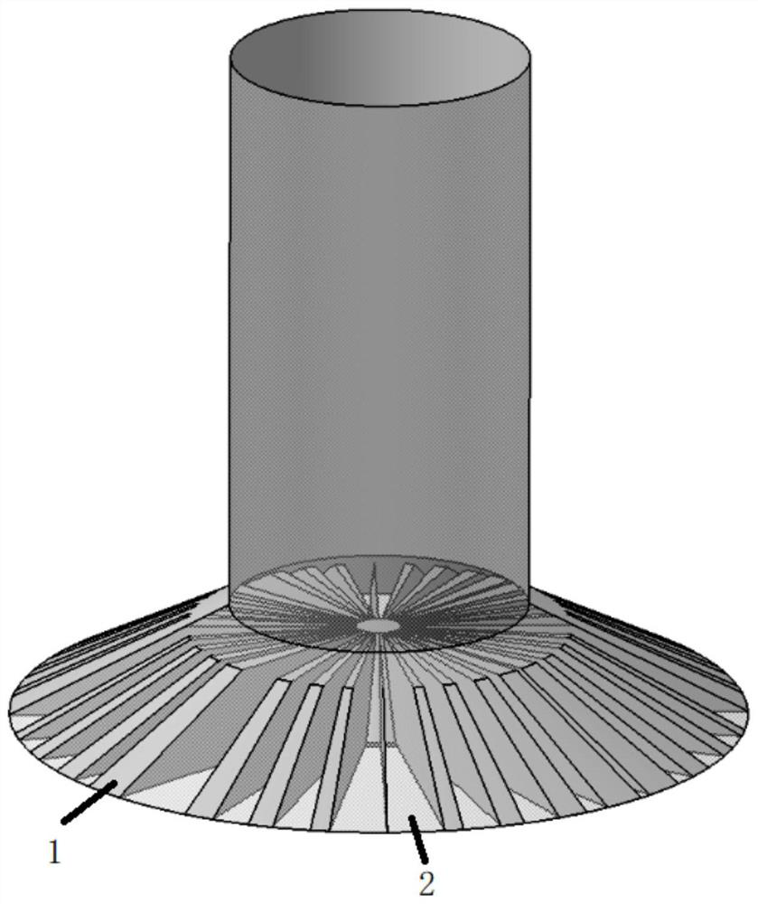
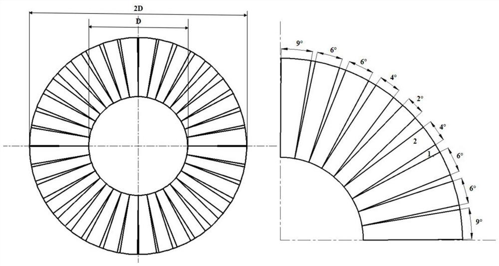
[0045] Such as figure 1 As shown, this embodiment proposes an air supply device, the circular tuyere device includes a blade fixing structure and 36 blades, all the blades take the axis of the blade fixing structure as a round point, and are connected around the blade fixing structure around the blade fixing structure A circular air supply device is formed, and there is a gap between adjacent blades. The gap forms an air duct, that is, an air outlet. The angle y of the air duct satisfies:

[0046]

[0047] Among them, y 0 is a constant, the value is 0.70479±0.35555;

[0048] w is a constant, the value is 1.07761±0.70802;

[0049] x c is a constant, the value is -0.74375±1.06275;

[0050] A is a constant with a value of 0.3823±0.32084;

[0051] A two-dimensional coordinate system is established with the axis of the blade fixed structure as a circle point, the horizontal positive direction of the two-dimensional coordinate system is specified as 0°, the air duct close to...

Embodiment 2

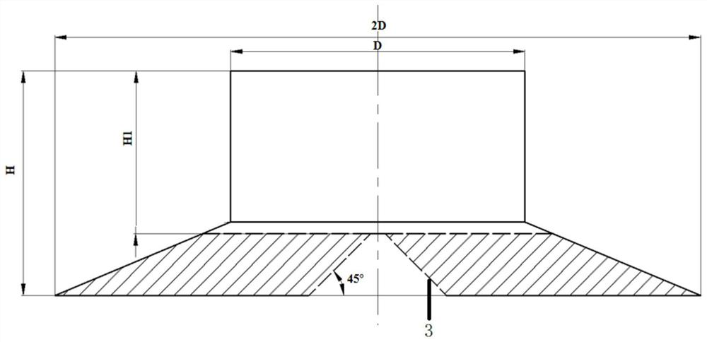
[0055] Such as figure 1 As shown, the present embodiment proposes an air supply device, including a blade fixing structure and 36 blades. The blade fixing structure is a circular platform; the blade is a space polyhedron closed structure, and the longitudinal section of the space polyhedron is a trapezoid. One of the sides of the trapezoid is set along the side of the circular platform, the length of the upper base adjacent to the one of the sides of the trapezoid is not less than the radius of the air outlet, and the length of the upper base adjacent to the one of the sides of the trapezoid is The length of the adjacent lower base is twice the length of the upper base plate, and the included angle between the generatrix of the circular platform and the bottom surface of the circular platform is preferably 45°.

[0056] In the above example, the diameter of the interface between the air supply device and the air pipe is D, that is, the length of the upper bottom is D; the leng...

Embodiment 3

[0060] This embodiment provides an air supply system with an air supply device, such as Figure 4 , the air supply system includes a blower unit, the blower unit transports the gas to the air supply area through the main pipeline and the branch pipeline, and then transports the gas into the square room through the circular tuyere device described in embodiment 1 or 2.

[0061] Further, the air blower unit includes a horizontal main pipe and a branch pipe connected with the horizontal main pipe. After the air blower unit sends the gas to the air supply area through the main pipe and the branch pipe, the air supply direction is changed through the bent pipe, and the bent pipe comes out The air outlet is located at the center of the top of the direction room and is perpendicular to the horizontal plane, and the circular air outlet device according to claim 1 is connected to the air outlet of the elbow.

[0062] The diameter of the interface between the air supply device and the e...


PUM


Abstract

The present invention proposes a low-Re number uniform air supply device, the air supply device includes a blade fixing structure and s blades, all the blades take the axis center of the blade fixing structure as a round point, and are connected around the blade fixing structure to form around the blade fixing structure The circular tuyere device has gaps between adjacent blades, and the gaps form the air outlets. Aiming at the current air supply status of square rooms, the present invention provides a low-heat uniform air supply device for square building space. Only one air supply device is installed in the center of the room, so that the air conditioner can send air throughout the entire square room. evenly distributed within.

Description

technical field [0001] The invention belongs to the technical field of ventilation, and relates to the improvement of ventilation in a ventilated and air-conditioned room, in particular to a low heat number uniform air supply device. Background technique [0002] With the rapid development of the national economy and the improvement of productivity, people spend more time working and studying indoors, and they pay more and more attention to the thermal comfort and air quality of the indoor environment. Good indoor air quality contributes to the improvement of people's health and work efficiency. Usually, by reasonably arranging the air supply outlets in the air-conditioned and ventilated room, the air jets from the air supply outlets are used to achieve the mixing of the air supply and indoor air, so as to achieve the purpose of ventilation and adjusting the temperature and humidity of the indoor air. As the terminal device of the air conditioning system and the starting de...

Claims


Application Information

Patent Timeline
IPC IPC(8): F24F13/06F24F13/02
CPCF24F13/02F24F13/06
Inventor 高然厉海萌来婷张恒春文诗豪鱼晟睿杜五一李安桂
Owner XI'AN UNIVERSITY OF ARCHITECTURE AND TECHNOLOGY
Why Eureka
Try Eureka