Medical disinfectant stirring and filtering equipment
A technology for filtering equipment and disinfectants, which is applied to mixer accessories, mixers with rotating stirring devices, chemical/physical processes, etc. It can solve the problems that the disinfectant cannot be blocked by the spraying equipment, and the disinfectant cannot be filtered.
- Summary
- Abstract
- Description
- Claims
- Application Information
AI Technical Summary
Problems solved by technology
Method used
Image
Examples
specific Embodiment approach 1
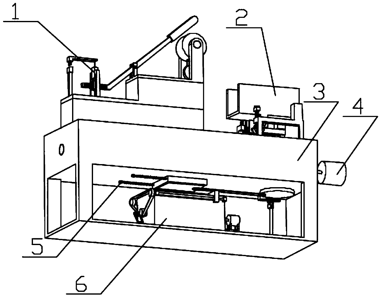
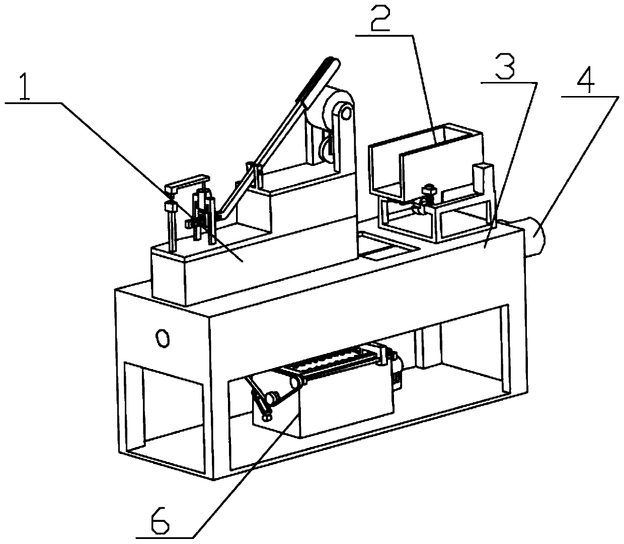
[0038] Combine below figure 1 , figure 2 , image 3 , Figure 4 , Figure 5 , Image 6 , Figure 7 , Figure 8 , Figure 9 , Figure 10 , Figure 11 , Figure 12 , Figure 13 , Figure 14 , Figure 15 , Figure 16 , Figure 17 , Figure 18 , Figure 19 , Figure 20 To illustrate this embodiment, the present invention relates to a stirring device, more specifically a stirring and filtering device for medical disinfectant, which includes a feeding start-stop mechanism 1, a feeding mechanism 2, a fuselage mechanism 3, a stirring mechanism 4, and a gate Mechanism 5, filter mechanism 6, the equipment can automatically add disinfectant, the equipment can control the start and stop of automatic feeding, the equipment can stir water and disinfectant into disinfectant, the equipment can automatically release the disinfectant, and the equipment can treat the disinfectant Filtration is performed and the device is self-cleaning.
[0039] The feed start-stop mechanism 1...
specific Embodiment approach 2
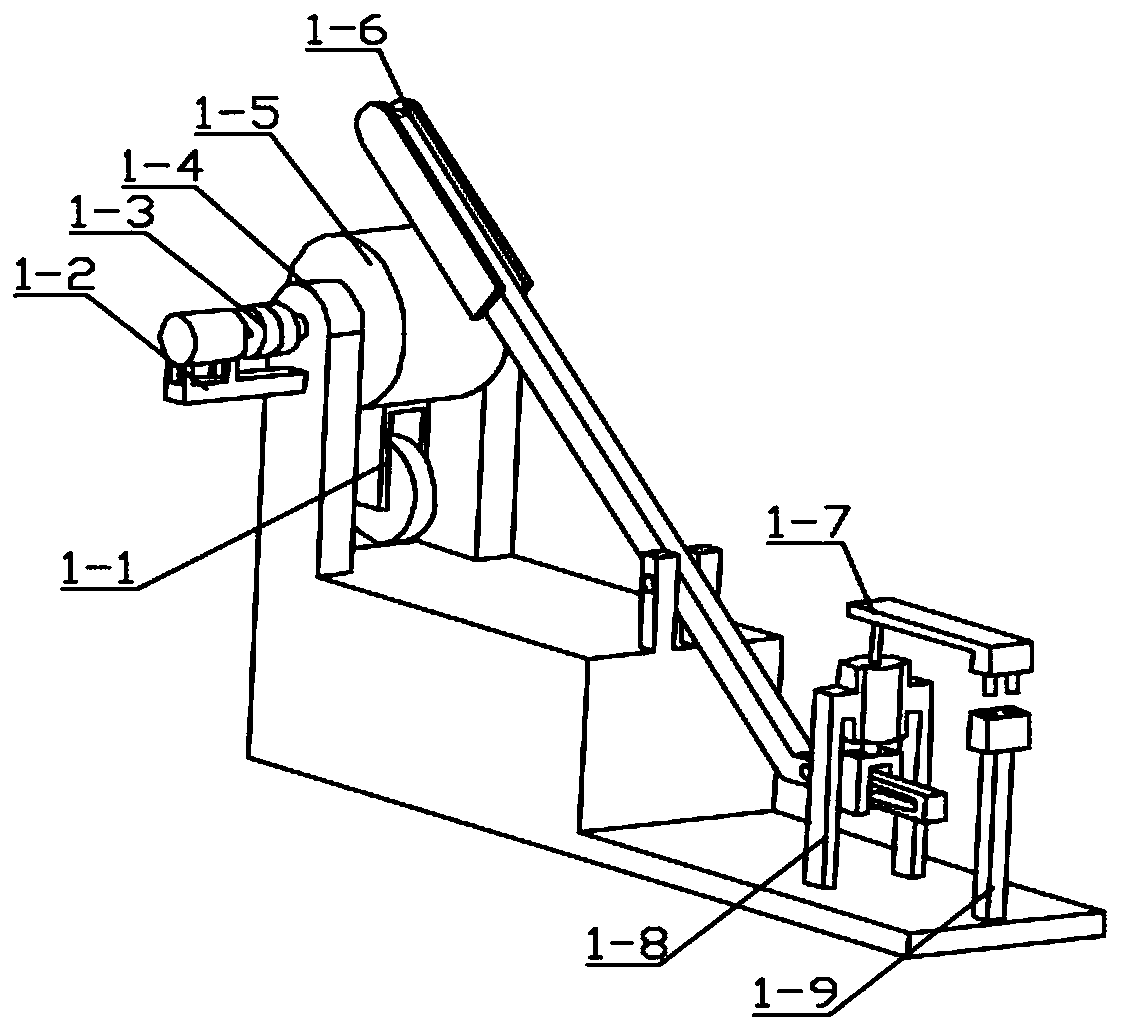
[0041] Combine below figure 1 , figure 2 , image 3 , Figure 4 , Figure 5 , Image 6 , Figure 7 , Figure 8 , Figure 9 , Figure 10 , Figure 11 , Figure 12 , Figure 13 , Figure 14 , Figure 15 , Figure 16 , Figure 17 , Figure 18 , Figure 19 , Figure 20 Describe this embodiment, this embodiment will further explain Embodiment 1, the described feeding start-stop mechanism 1 includes a push wheel 1-1, a motor 1-2, a shaft coupling 1-3, a support 1-4, a belt shaft Rotating wheel 1-5, matching mechanism 1-6, sliding plug mechanism 1-7, sliding chamber mechanism 1-8, socket 1-9, push wheel 1-1 links to each other with band shaft turning wheel 1-5, band shaft turning wheel 1-5 is connected with the motor 1-2 through the coupling 1-3, the motor 1-2 is connected with the support 1-4, the connection mode of the support 1-4 and the belt shaft rotating wheel 1-5 is the bearing connection, and the matching mechanism 1 The connection mode between -6 and supp...
specific Embodiment approach 3
[0043] Combine below figure 1 , figure 2 , image 3 , Figure 4 , Figure 5 , Image 6 , Figure 7 , Figure 8 , Figure 9 , Figure 10 , Figure 11 , Figure 12 , Figure 13 , Figure 14 , Figure 15 , Figure 16 , Figure 17 , Figure 18 , Figure 19 , Figure 20 Describe this embodiment, this embodiment will further explain Embodiment 1. The described feeding mechanism 2 includes a feeding hopper 2-1, a vibration driving mechanism 2-2, a vibration supporting mechanism 2-3, and the feeding hopper 2-1 and the vibration The driving mechanism 2-2 is connected, and the feed hopper 2-1 is connected with the vibration support mechanism 2-3; the vibration driving mechanism 2-2 includes a vibration motor 2-2-1, a vibration motor pulley 2-2-2, and a belt 2-2- 3. Transmission pulley 2-2-4, shaft 2-2-5, eccentric wheel 2-2-6, vibration motor 2-2-1 is connected with vibration motor pulley 2-2-2, vibration motor pulley 2-2- 2 is connected with belt 2-2-3, belt 2-2-3 i...
PUM
 Abstract
Description
Claims
Application Information
 - R&D
- Intellectual Property
- Life Sciences
- Materials
- Tech Scout
- Unparalleled Data Quality
- Higher Quality Content
- 60% Fewer Hallucinations
Browse by: Latest US Patents, China's latest patents, Technical Efficacy Thesaurus, Application Domain, Technology Topic, Popular Technical Reports.
© 2025 PatSnap. All rights reserved.Legal|Privacy policy|Modern Slavery Act Transparency Statement|Sitemap|About US| Contact US: help@patsnap.com


