Metal parts stamping system

A technology for metal fittings to be stamped, applied in metal processing equipment, feeding devices, manufacturing tools, etc., can solve the problems of inaccurate stamping dimensions and low quality of metal fittings, and achieve the effect of improving quality and avoiding serious wear

Active Publication Date: 2021-02-26
武汉宏升鑫汽车部件有限公司
View PDF1 Cites 0 Cited by
  • Summary
  • Abstract
  • Description
  • Claims
  • Application Information

AI Technical Summary

Problems solved by technology

[0004] There are following defects in the above-mentioned existing technical solutions: because there is generally a short distance between the leveling mechanism and the stamping mechanism, and because the die mounting base of the stamping mechanism is generally designed to be relatively large so as to install stamping dies of various sizes , so there will be a distance between the entrance of the stamping mechanism and the entrance of the stamping die, so the strip steel generally has a length of about 2-3 meters from the output of the leveling mechanism to the entrance of the stamping die. Under the action, this section of strip steel will be in a downward concave state, which will cause the strip steel to be transported to the stamping die at a certain inclination angle, which will easily cause the problem that the stamping size is not accurate enough, and the quality of the metal parts produced is not high, so Room for improvement

Method used


Image

  • Metal parts stamping system
  • Metal parts stamping system
  • Metal parts stamping system

Examples


Embodiment 1

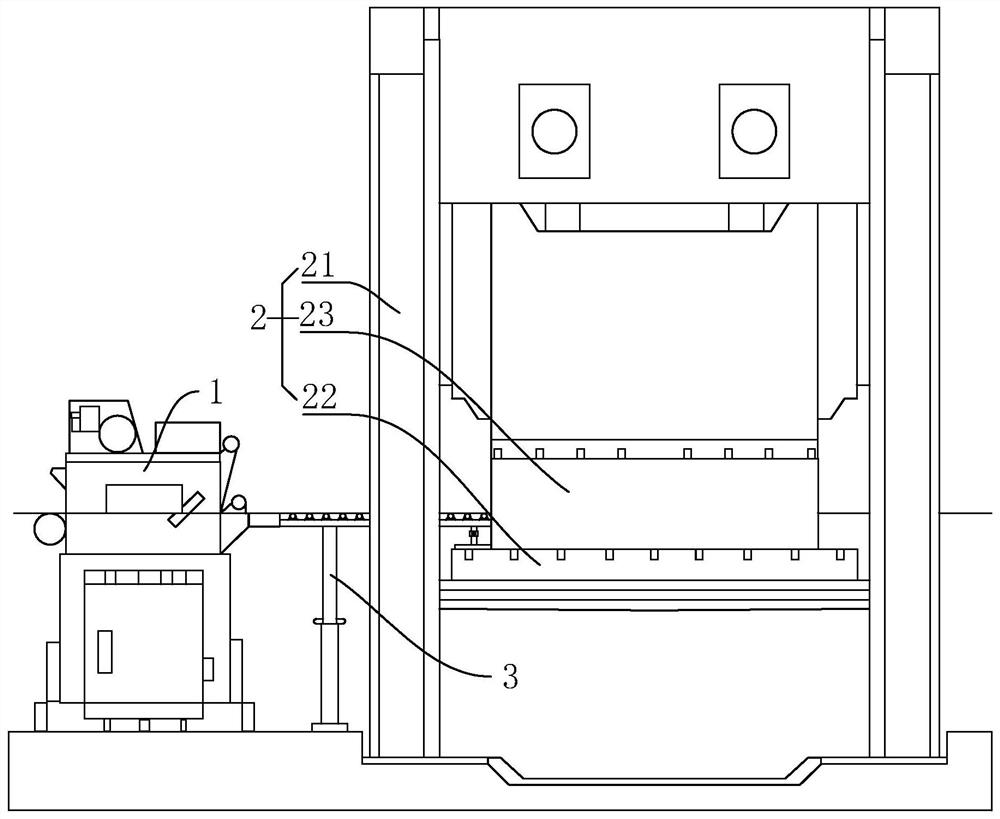
[0038] refer to figure 1 , is a stamping system for metal fittings disclosed in the present invention, comprising: a leveling mechanism 1, a stamping mechanism 2 and a supporting mechanism 3; The side near the leveling mechanism 1 is provided with a steel strip inlet, the support mechanism 3 is arranged on the ground and / or on the stamping mechanism 2, one end of the support mechanism 3 is connected to the output end of the leveling mechanism 1, and the other end of the support mechanism 3 Connecting with the input end of the stamping die 23, the top surface of the support mechanism 3 supports the steel strip to be stamped so as to keep the strip steel to be stamped in a horizontal state.

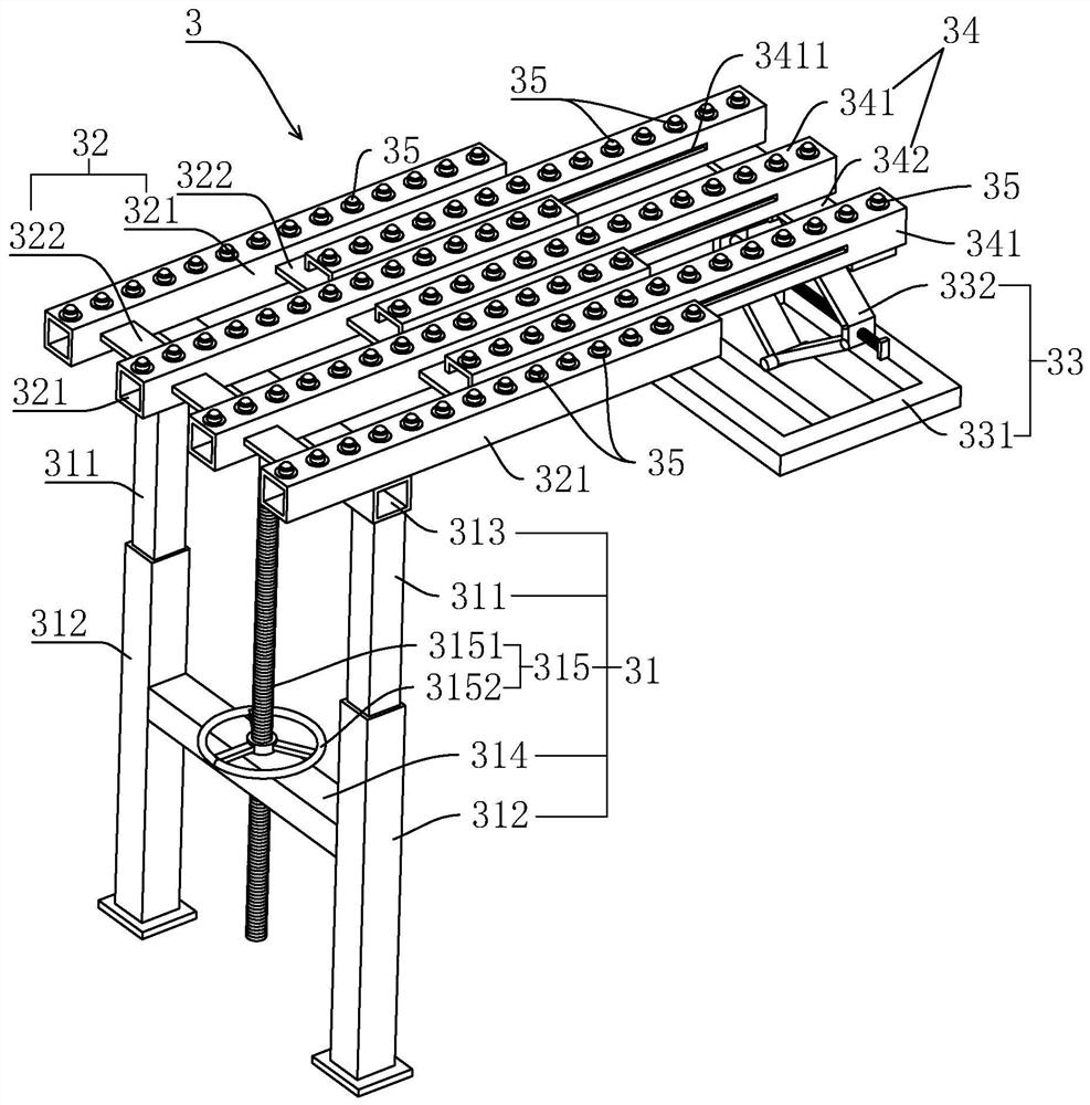
[0039] combine figure 1 and figure 2 As shown, the support mechanism 3 includes: a first support portion 31, a first horizontal frame 32, a second support portion 33, a second horizontal frame 34 and a rolling support 35, and the rolling support 35 is located on the first horizontal fram...

Embodiment 2

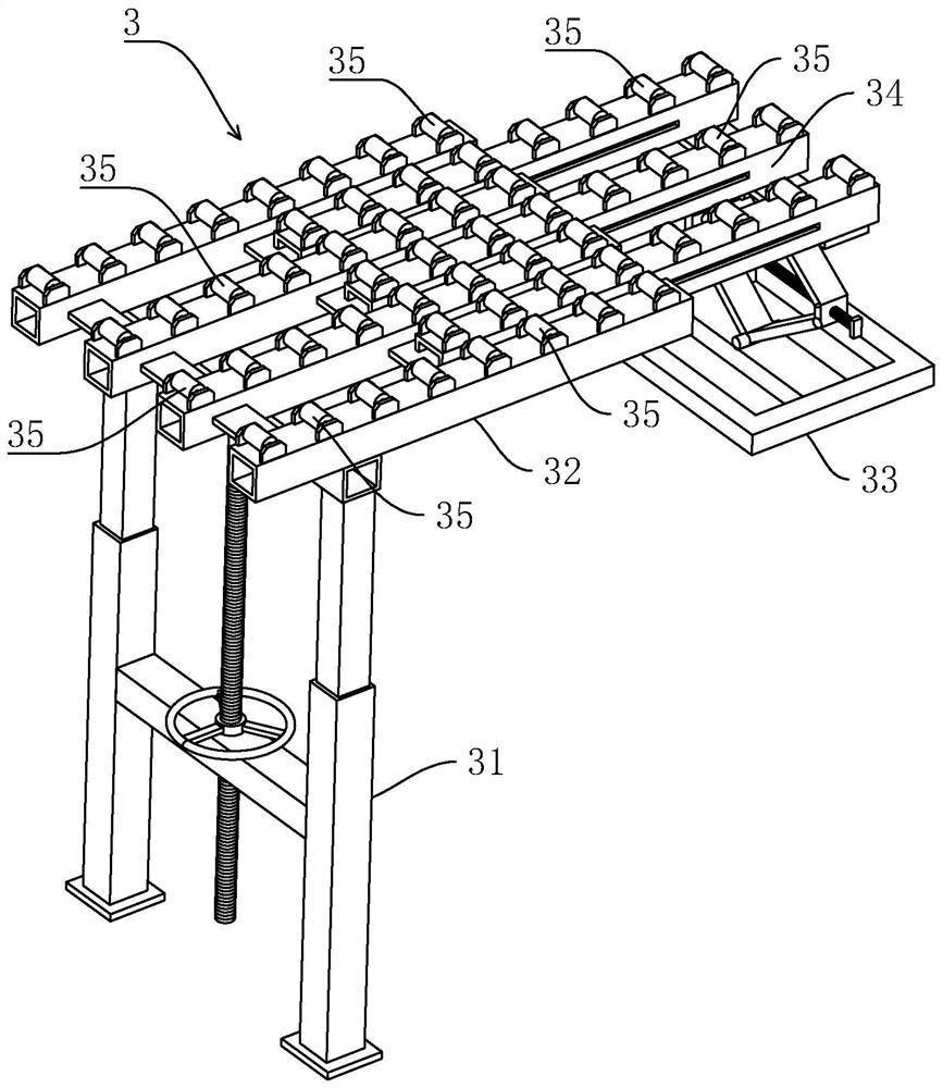
[0052] refer to figure 1 and image 3 , is a stamping system for metal fittings disclosed in the present invention. The difference from Embodiment 1 is that the rolling support 35 is specifically an idler, and the idler is rotatably assembled on the upper surfaces of the first horizontal frame 32 and the second horizontal frame 34 , the rollers are arranged horizontally, and the layout direction of the rollers is perpendicular to the conveying direction of the strip to be stamped. The rollers can be purchased directly from the market, which is convenient to purchase, low in cost, and simple to install.


PUM


Abstract

The invention relates to a stamping system for metal accessories, which relates to the technical field of auto parts production, including: a leveling mechanism, a stamping mechanism and a supporting mechanism; A strip steel inlet is arranged on one side close to the leveling mechanism, the support mechanism is arranged on the ground and / or on the stamping mechanism, one end of the support mechanism is connected to the output end of the leveling mechanism, and the The other end of the support mechanism is in contact with the input end of the stamping die, and the top surface of the support mechanism supports the steel strip to be stamped so as to keep the strip steel to be stamped in a horizontal state. The invention has the effects of preventing the steel strip to be stamped from being sunken under the action of gravity, maintaining horizontal conveyance before the strip steel to be stamped enters the stamping die, and indirectly improving the quality of the metal fittings produced.

Description

technical field [0001] The invention relates to the technical field of auto parts production, in particular to a stamping system for metal parts. Background technique [0002] Most auto parts are formed by stamping metal sheets. During the production process of auto parts, metal parts of different shapes and specifications will be made by unwinding, leveling, stamping and other processes. With the development of society and the automobile industry, people The processing requirements of metal accessories are getting higher and higher. [0003] A Chinese utility model patent with the announcement number CN207823774U has now been retrieved, which discloses a leveling feeder, including: a feeding mechanism, a leveling mechanism, and a punching mechanism arranged in sequence, and the feeding mechanism is used to stretch the rolled strip steel , the leveling mechanism is used for leveling the stretched steel strip and transporting it to the stamping mechanism. A stamping die is i...

Claims


Application Information

Patent Timeline
Patent Type & Authority Patents(China)
IPC IPC(8): B21D43/00B21D22/02
CPCB21D22/02B21D43/003
Inventor 张黎涛
Owner 武汉宏升鑫汽车部件有限公司
Why Eureka
Try Eureka