Pneumatic or hydraulic single-seat regulating valve
A control valve, hydraulic technology, applied in the field of control valves, can solve the problems of valve stuck, damaged sealing surface, easy to block, etc., to achieve the effect of preventing damage to the sealing pair, preventing blockage, and long service life
- Summary
- Abstract
- Description
- Claims
- Application Information
AI Technical Summary
Problems solved by technology
Method used
Image

Examples
Embodiment Construction
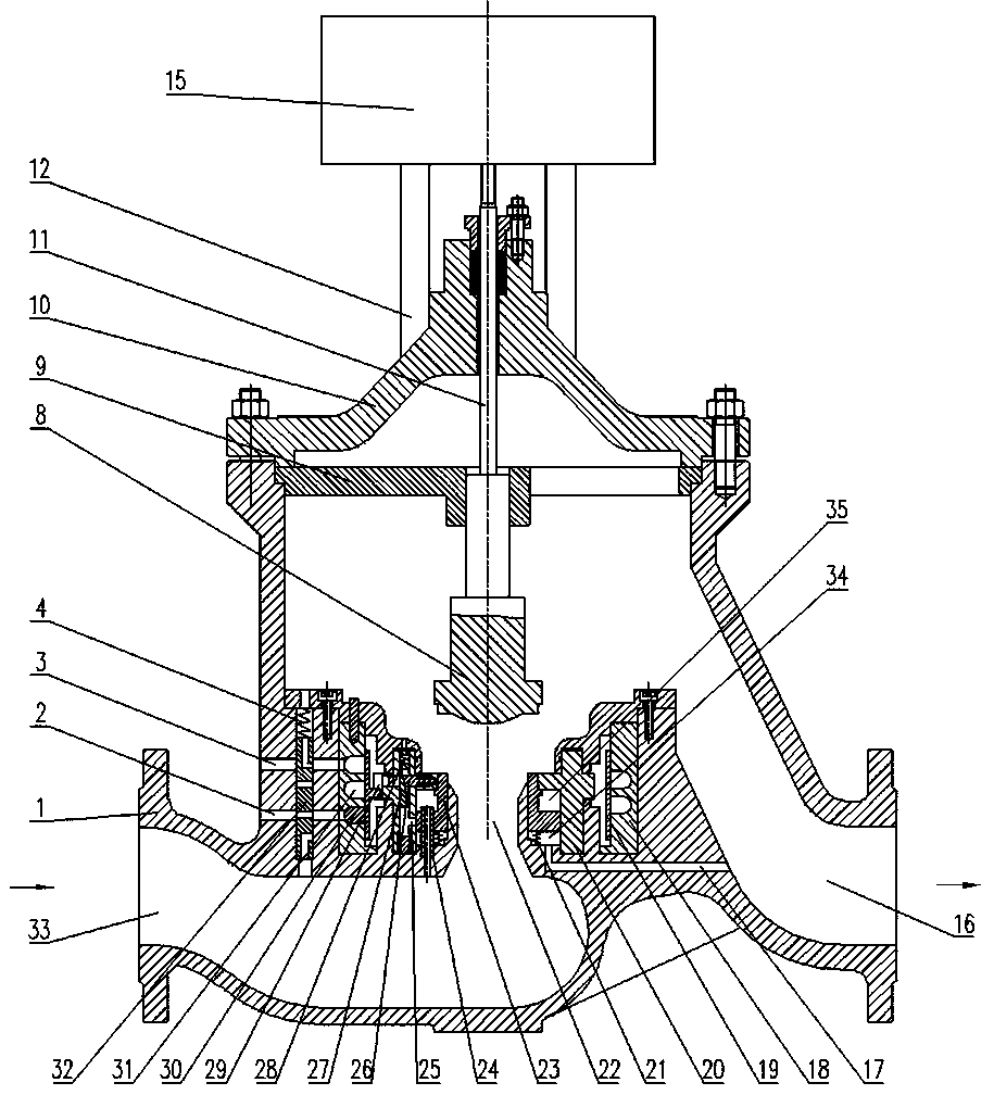
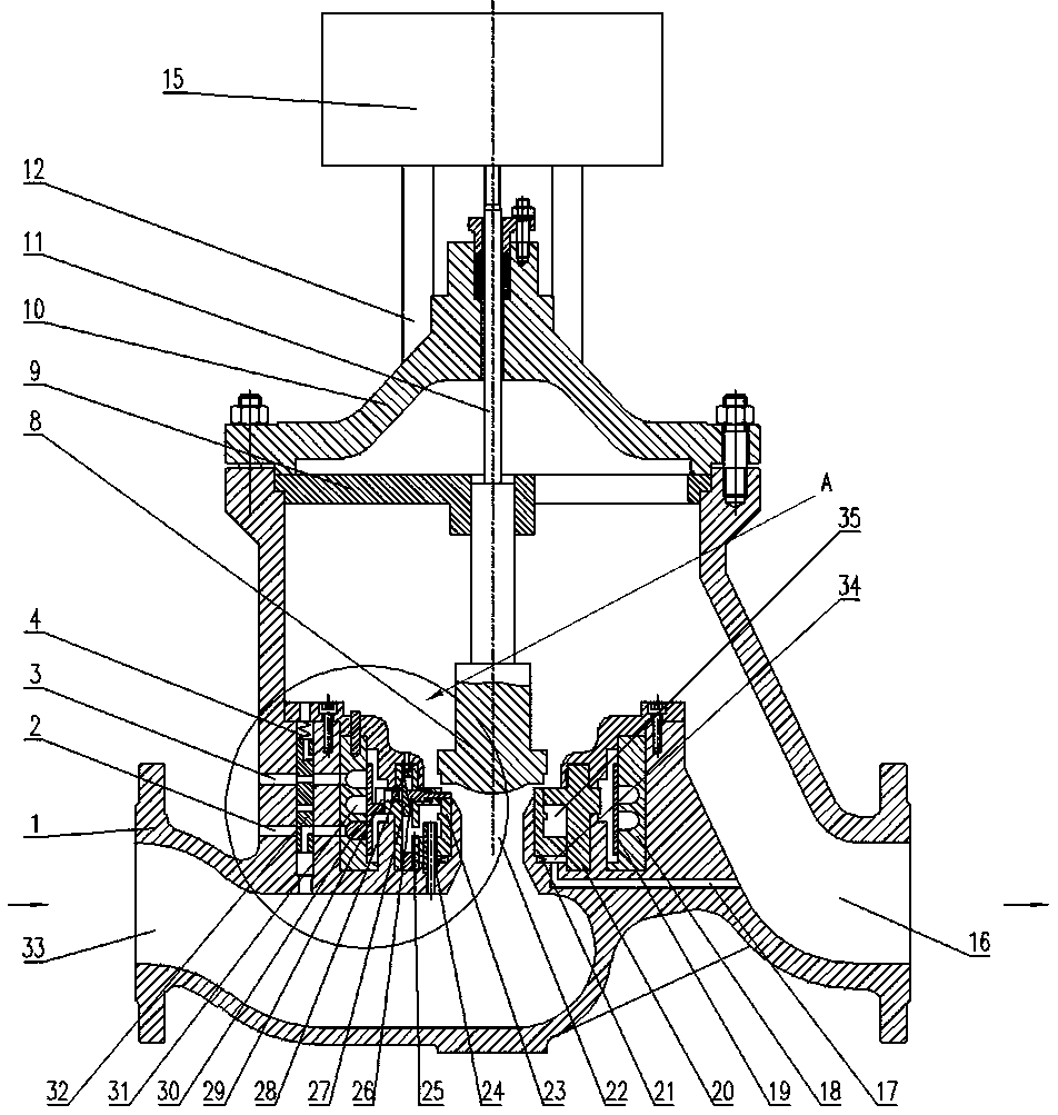
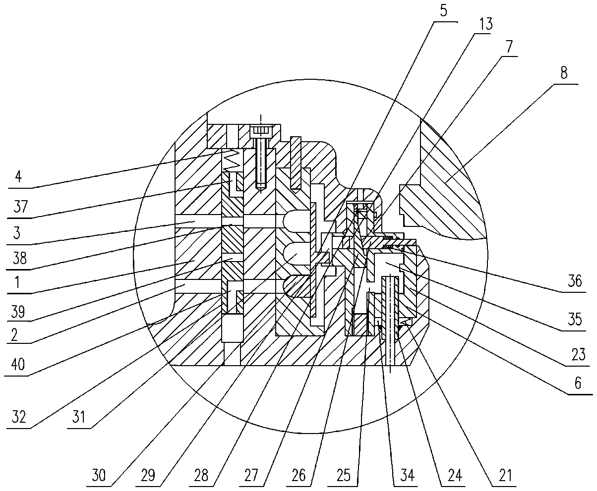
[0013] Accompanying drawing has shown structure of the present invention, further illustrates its relevant details below again in conjunction with accompanying drawing. The pneumatic or hydraulic single-seat regulating valve includes a valve body 1, a valve cover 10 and a valve stem 11. The valve body 1 is provided with an inlet passage 33 and an outlet passage 16, and the inlet passage 33 and the outlet passage 16 pass through a central flow. The valve seat 23 and the valve disc 8 forming a sealing pair are arranged at the center channel 22, and the valve disc 8 is driven by the valve stem 11 to move up and down. The first cavity, the second cavity, the third cavity and the fourth cavity are provided in sequence to the outside; the valve seat 23 can move up and down in the first cavity, and the upper end of the valve seat 23 can move out of the first cavity. A cavity, the lower end of the valve seat 23 is provided with a step 6, and the step 6 divides the first cavity into an...
PUM
 Abstract
Description
Claims
Application Information
 - R&D
- Intellectual Property
- Life Sciences
- Materials
- Tech Scout
- Unparalleled Data Quality
- Higher Quality Content
- 60% Fewer Hallucinations
Browse by: Latest US Patents, China's latest patents, Technical Efficacy Thesaurus, Application Domain, Technology Topic, Popular Technical Reports.
© 2025 PatSnap. All rights reserved.Legal|Privacy policy|Modern Slavery Act Transparency Statement|Sitemap|About US| Contact US: help@patsnap.com