Ore loading and unloading hopper wheel position inspection tool

A technology for loading and unloading materials and ore, applied in the direction of measuring devices, mechanical devices, mechanical measuring devices, etc., can solve the problems of large cumulative error, low inspection efficiency, spatial position error, etc., to achieve true inspection results, improve inspection efficiency, The effect of improving machining accuracy

Inactive Publication Date: 2020-01-03
TIANJIN BAO HONGYUAN MACHINERY MFG
View PDF6 Cites 0 Cited by
  • Summary
  • Abstract
  • Description
  • Claims
  • Application Information

AI Technical Summary

Problems solved by technology

The traditional method is manual measurement, which mainly has the following defects: firstly, the inspection efficiency is low; secondly, due to certain errors in manual measurement, the cumulative error after multiple measurements is large, resulting in untrue inspection results; finally, if Insufficient perpendicularity of adjacent surfaces during measurement, although it will not affect the measurement results, will lead to spatial position errors, which will also lead to false inspection results and reduce the effectiveness of inspection

Method used


Image

  • Ore loading and unloading hopper wheel position inspection tool
  • Ore loading and unloading hopper wheel position inspection tool

Examples


Embodiment 1

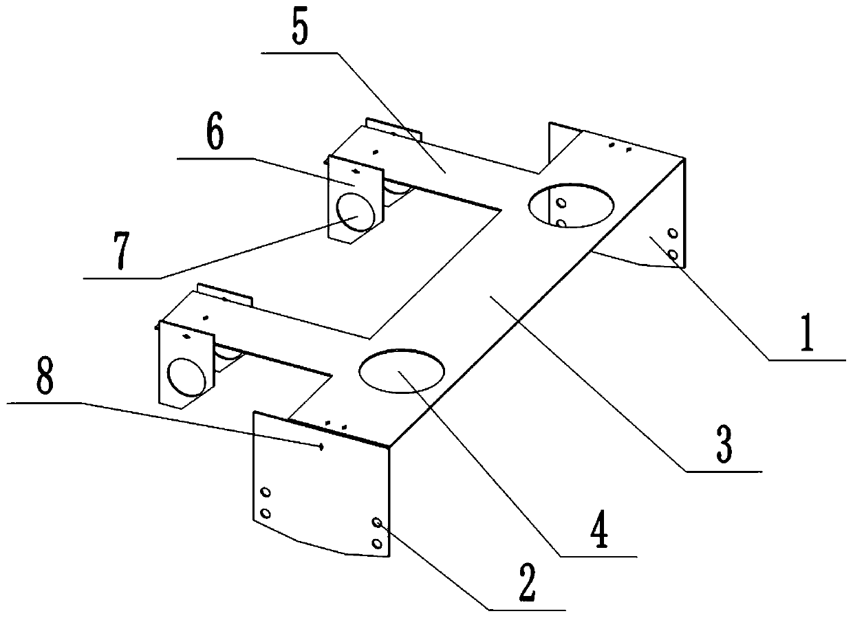
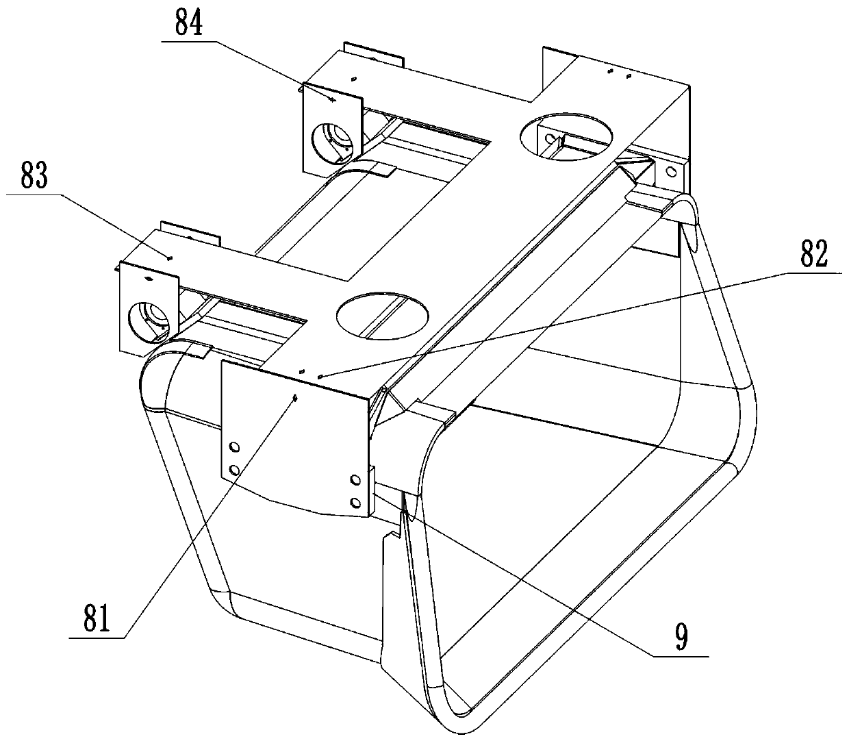
[0025] A wheel position inspection tool for an ore loading and unloading hopper, comprising two positioning side plates 1, the positioning side plate 1 is provided with a positioning hole 2 in cooperation with the connecting holes on the connecting plates 9 on both sides of the ore loading and unloading hopper, and the two positioning side plates 1 1 is provided with a top plate 3, the top plate 3 is vertically arranged with the positioning side plate 1, the two sides of the top plate 3 are fixedly connected with the tops of the two positioning side plates 1 respectively, and the top plate 3 is provided with two driving wheel observation holes 4 , during the inspection, the two driving wheel observation holes 4 are respectively located directly above the two driving wheel installation positions on the top of the ore loading and unloading hopper,

[0026] Two support plates 5 are fixed on the side of the top plate 3 close to the guide wheels of the ore loading and unloading hopp...

Embodiment 2

[0031] A wheel position inspection tool for an ore loading and unloading hopper, comprising two positioning side plates 1, the positioning side plate 1 is provided with a positioning hole 2 in cooperation with the connecting holes on the connecting plates 9 on both sides of the ore loading and unloading hopper, and the two positioning side plates 1 1 is provided with a top plate 3, the top plate 3 is vertically arranged with the positioning side plate 1, the two sides of the top plate 3 are fixedly connected with the tops of the two positioning side plates 1 respectively, and the top plate 3 is provided with two driving wheel observation holes 4 , during the inspection, the two driving wheel observation holes 4 are respectively located directly above the two driving wheel installation positions on the top of the ore loading and unloading hopper,

[0032] Two support plates 5 are fixed on the side of the top plate 3 close to the guide wheels of the ore loading and unloading hopp...


PUM


Abstract

The invention relates to an ore loading and unloading hopper wheel position inspection tool. The ore loading and unloading hopper wheel position inspection tool comprises two positioning side plates I, wherein positioning holes are formed in the positioning side plates I; a top plate is arranged between the two positioning side plates I; two driving wheel observation holes are formed in the top plate; two support plates are fixedly arranged on one side, close to an ore loading and unloading hopper guide wheel, of the top plate; positioning side plates II are fixedly arranged on the two sides of the support plate; guide wheel observation holes are formed in the positioning side plates II; and the guide wheel observation holes and the guide wheel mounting positions are arranged coaxially ininspection. When the inspection tool is in use, the inspection tool is fixedly connected to connecting plates on the two sides of the ore loading and unloading hopper through the positioning holes, sothat the relative positions of the driving wheel installation positions, guide wheel installation positions and other surfaces of the ore loading and unloading hopper can be inspected. The mode is simple and convenient to operate, the inspection efficiency is improved, the accumulation error caused by manual multi-time measurement and insufficient perpendicularity of adjacent surfaces is avoided,and therefore, the machining precision is improved, and the inspection result is true and reliable.

Description

technical field [0001] The invention relates to the technical field of inspection tooling, in particular to an ore loading and unloading hopper wheel position inspection tool. Background technique [0002] After the ore loading and unloading hopper is manufactured, it is necessary to inspect the relative positions of the driving wheel installation position, guide wheel installation position and other sides of the ore loading and unloading hopper, which involves multiple sets of parameters. The traditional method is manual measurement, which mainly has the following defects: firstly, the inspection efficiency is low; secondly, due to certain errors in manual measurement, the cumulative error after multiple measurements is large, resulting in untrue inspection results; finally, if Insufficient verticality of adjacent surfaces during measurement will not affect the measurement results, but will lead to spatial position errors, which will also lead to false inspection results an...

Claims


Application Information

Patent Timeline
Patent Type & Authority Applications(China)
IPC IPC(8): G01B5/255
CPCG01B5/255
Inventor 周洋张献
Owner TIANJIN BAO HONGYUAN MACHINERY MFG
Why Eureka
Try Eureka