Eureka AIR delivers breakthrough ideas for toughest innovation challenges, trusted by R&D personnel around the world.

Remote control device of running route of special vehicle

A technology for driving routes and special vehicles, applied in the direction of telephone structure, signal transmission system, instruments, etc., can solve the problems of inconvenient installation and fixation of display devices, inconvenient angle adjustment, complicated operation, etc., to reduce the number of wires that are too cluttered and too many , The effect of preventing gear rotation and convenient installation

Inactive Publication Date: 2020-01-03
SOUTHWEST COMP
View PDF17 Cites 1 Cited by
  • Summary
  • Abstract
  • Description
  • Claims
  • Application Information

AI Technical Summary

Problems solved by technology

[0003] The purpose of the present invention is to solve the shortcomings in the prior art, such as: the existing special vehicle remote control device is not convenient for the user to install and fix the display device, it is not convenient for the user to adjust the angle, the operation is complicated, and it is inconvenient to store and carry. Wire charging has time and place restrictions, and it is not convenient to fix the battery board. The proposed method is convenient for users to install and fix the display device, and it is convenient for users to adjust the angle according to their own needs. It is easy to operate, convenient to store and carry, and the battery board It is able to store electricity for the device, avoiding excessive clutter caused by too many internal circuits of the device, and a remote control device for driving routes of special vehicles

Method used

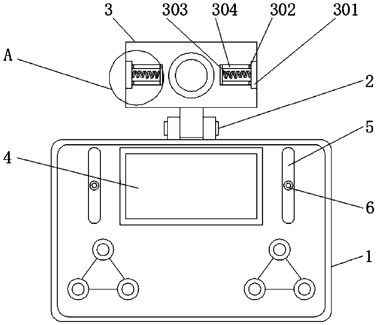
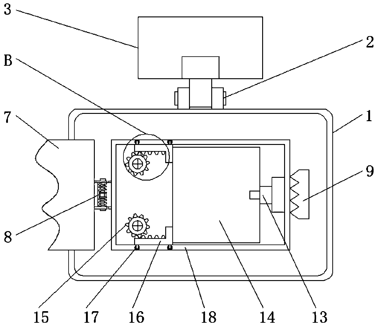
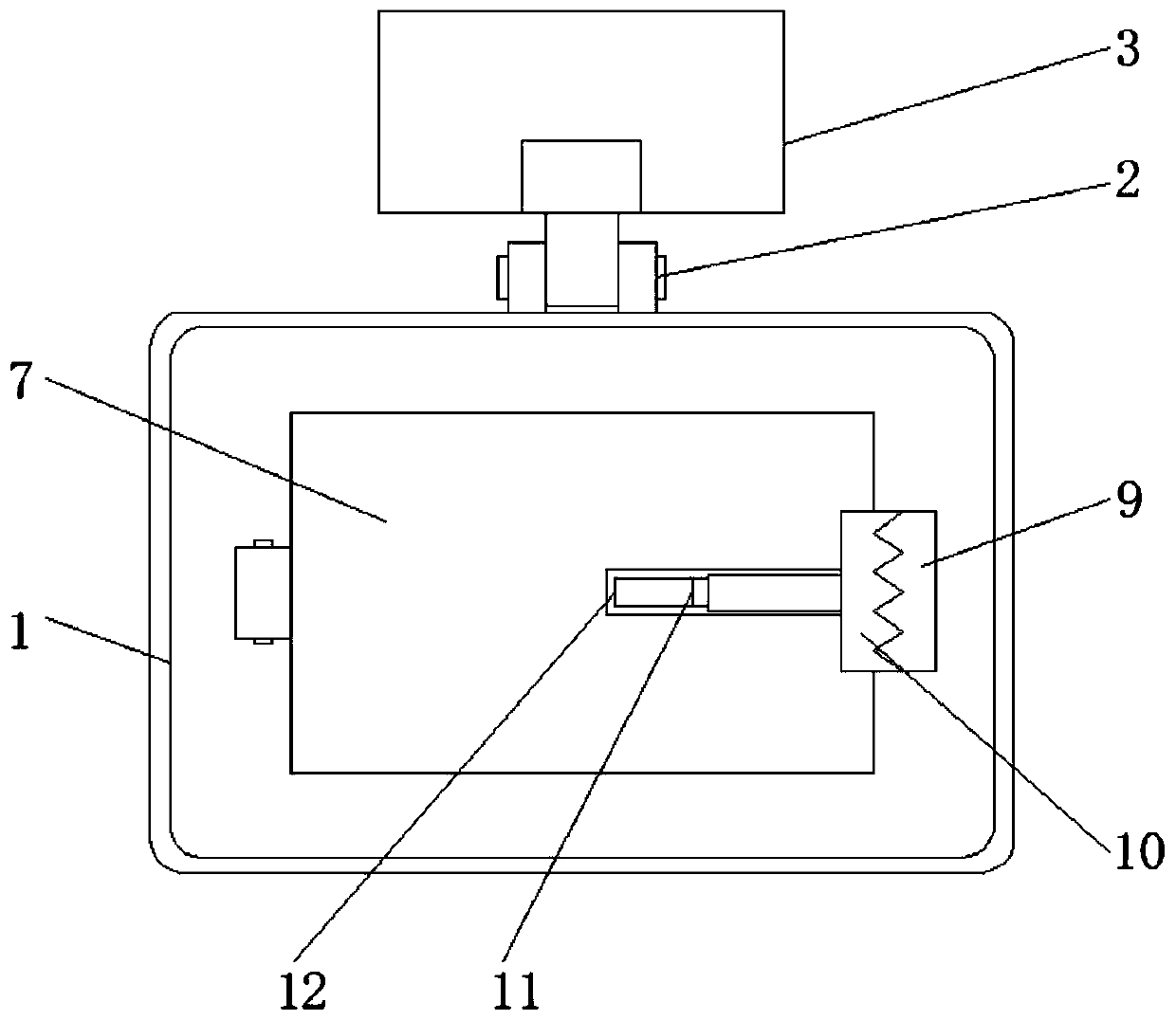

Image

  • Remote control device of running route of special vehicle
  • Remote control device of running route of special vehicle
  • Remote control device of running route of special vehicle

Examples


Embodiment Construction

[0023] The following will clearly and completely describe the technical solutions in the embodiments of the present invention with reference to the accompanying drawings in the embodiments of the present invention. Obviously, the described embodiments are only some, not all, embodiments of the present invention.

[0024] In describing the present invention, it should be understood that the terms "upper", "lower", "front", "rear", "left", "right", "top", "bottom", "inner", " The orientation or positional relationship indicated by "outside", etc. is based on the orientation or positional relationship shown in the drawings, and is only for the convenience of describing the present invention and simplifying the description, rather than indicating or implying that the referred device or element must have a specific orientation, so as to Specific orientation configurations and operations, therefore, are not to be construed as limitations on the invention.

[0025] refer to Figure ...


PUM


Abstract

The invention relates to the technical field of remote control devices of special vehicles, and discloses a remote control device of a running route of a special vehicle. The device includes a remotecontroller main-body, a rear cover and a plug. A rotating shaft is mounted above the remote controller main-body. A fixing mechanism is connected outside the rotating shaft. A placement slot is reserved at a middle position of the remote controller main-body. First clamping blocks are mounted at edge sides of the placement slot. Rotating blocks are mounted at middle positions of the first clampingblocks. The rear cover is located at a back surface of the remote controller main-body. A lock pin is mounted at one end of the rear cover, and a second clamping block is mounted at the other end ofthe rear cover. A third clamping block is connected to an edge side of the second clamping block. A second sliding block is mounted at an end part of the third clamping block. According to the device,installation and fixing of a user on a display device are facilitated, operation of adjusting an angle by the user according to needs thereof is facilitated, operation is simple, storage and carryingare convenient, a battery board can carry out power storage for the device, and a phenomenon of disorder caused by excessive internal lines of the device is avoided.

Description

technical field [0001] The invention relates to the technical field of remote control devices for special vehicles, in particular to a remote control device for driving routes of special vehicles. Background technique [0002] When special vehicles are driving, remote control devices are required to survey the driving routes, and the remote control devices can electronically control the driving routes of special vehicles, so that users can drive safely when driving special vehicles. Contents of the invention [0003] The purpose of the present invention is to solve the shortcomings in the prior art, such as: the existing special vehicle remote control device is not convenient for the user to install and fix the display device, it is not convenient for the user to adjust the angle, the operation is complicated, and it is inconvenient to store and carry. Wire charging has time and place restrictions, and it is not convenient to fix the battery board. The proposed method is c...

Claims


Application Information

Patent Timeline
Patent Type & Authority Applications(China)
IPC IPC(8): G08C17/00G08C19/00G08C23/00H04M1/04
CPCG08C17/00G08C19/00G08C23/00H04M1/04
Inventor 宋璞裕方晓帆付如意冉鲜
Owner SOUTHWEST COMP
Why Eureka
Eureka Blog
Learn More