
A device and method for precise positioning of a rotary-type rotor-stator bearing a large axial load

An axial load and precise positioning technology, applied in workpiece clamping devices, manufacturing tools, etc., can solve the problems of precise positioning and the difficulty of rotor axial load, and achieve the effect of good popularization, strong practicability and simple method.

Active Publication Date: 2021-09-28
AECC AVIATION POWER CO LTD
View PDF3 Cites 0 Cited by
  • Summary
  • Abstract
  • Description
  • Claims
  • Application Information

AI Technical Summary

Problems solved by technology

[0007] The purpose of the present invention is to provide a rotary-type rotor bearing large axial load precise positioning device and method to solve the problem of difficult precise positioning and axial load bearing of the rotor during the assembly process of the low-pressure turbine unit body

Method used


Image

  • A device and method for precise positioning of a rotary-type rotor-stator bearing a large axial load
  • A device and method for precise positioning of a rotary-type rotor-stator bearing a large axial load
  • A device and method for precise positioning of a rotary-type rotor-stator bearing a large axial load

Examples


Embodiment approach

[0053] Precise Positioning Assembly Scheme Analysis

[0054] (1) Accurate positioning method of the rotary stator bearing large axial load:

[0055] ①Technical requirements: The rotor and stator can be precisely positioned in the axial direction, bear the weight of the rotor in the axial direction, and the rotor and stator can realize relative rotation;

[0056] ②Environmental structure:

[0057] a. The rotor part only exposes the tail section of the low vortex shaft at the load-bearing casing. The inner hole of the tail section has an annular groove structure, and the rear edge is a plane.

[0058] b. The bearing seat structure of the load-bearing casing is in radial contact with the bearing to transmit force, so axial positioning and bearing cannot be carried out.

[0059] c. The rear part of the load-bearing casing forms an open small space cone cavity, and the bearing seat structure has a mounting edge with threaded holes to connect with the load-bearing casing.

[0060...


PUM


Abstract

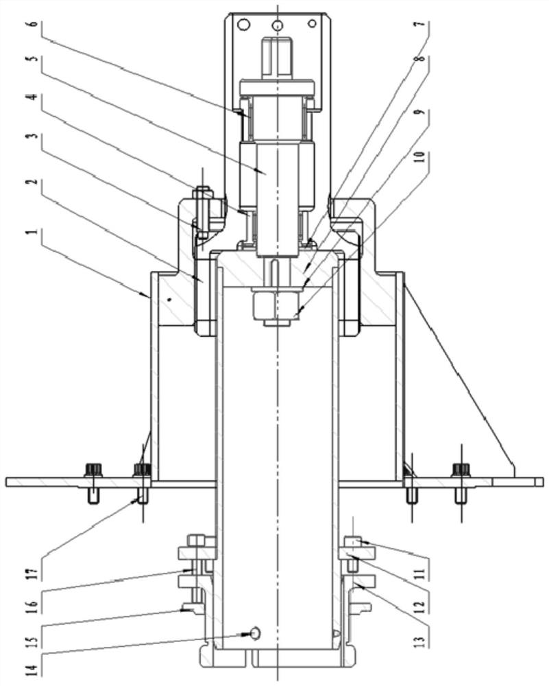
The invention discloses a rotary-type rotor-stator precise positioning device and a method for bearing large axial loads. The rotary-type rotor-stator precise positioning device for bearing large axial loads includes a connecting plate structure, an externally threaded sleeve for adjustment, a drive rod, a first A needle roller thrust bearing, a second needle roller thrust bearing, a cylinder body and a fan-shaped body, the connection plate structure includes an internal thread sleeve, and the internal thread sleeve is provided with a first through hole for the adjustment of the external thread sleeve to pass through. The external threaded sleeve is threadedly connected with the internal threaded sleeve, and the external threaded sleeve is adjusted to be connected with the driving rod through the first needle roller thrust bearing and the second needle roller thrust bearing installed oppositely, and the driving rod is connected with one end of the cylinder; the cylinder The other end of the fan is connected to the large end of the fan-shaped body, and the small end of the fan-shaped body is provided with a boss to cooperate with the annular groove at the inner hole of the tail section of the low-pressure turbine shaft unit body. The invention has the advantages of accurate positioning, safety and reliability, high bearing capacity and accurate axial position adjustment.

Description

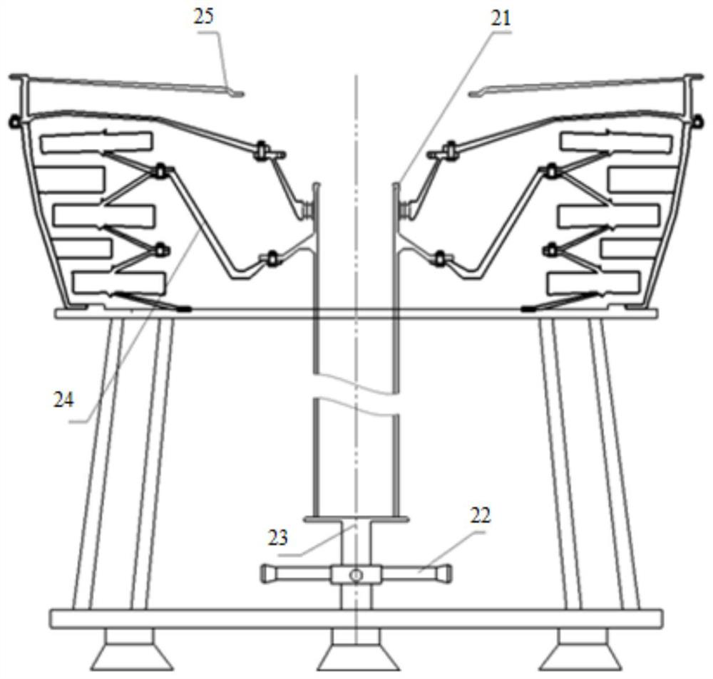
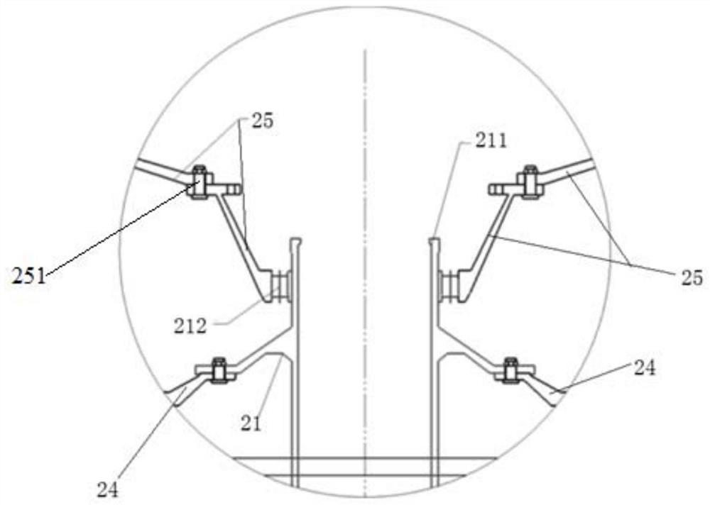
technical field [0001] The invention belongs to the field of assembly, and in particular relates to a precise positioning device and method for a rotating stator bearing a large axial load. Background technique [0002] A certain type of aero-engine low-pressure turbine unit includes three parts: the low-pressure turbine rotor-stationary sub-unit 24 , the low-pressure turbine shaft unit 21 and the low-pressure turbine load-bearing casing unit 25 . The low-pressure turbine rotor adopts a disc-drum structure, the stator casing adopts an integral structure, and the turbine discs of each stage are connected by bolts. According to the structural characteristics of the rotor-stator, the rotor-stator unit of the low-pressure turbine is vertically assembled using the rotor-stator alternate process route. The low-pressure turbine shaft unit is connected with the supporting cone of the rotor-stator unit through precision bolts, and the rear-end fulcrum bearing 212 is radially positio...

Claims


Application Information

Patent Timeline
Patent Type & Authority Patents(China)
IPC IPC(8): B25B11/02
CPCB25B11/02
Inventor 蔡鹏虎宋树林马涛黄健崔宝锋丰婷婷焦晓冉
Owner AECC AVIATION POWER CO LTD
Learn More