Two-stage oil-water separator

A technology of oil-water separation and oil-water separation device, applied in liquid separation, separation method, multi-stage water treatment, etc., can solve problems such as easy air suction, temperature rise failure, and easy pump failure.

Inactive Publication Date: 2020-01-07
张 锦 纶
View PDF9 Cites 0 Cited by
  • Summary
  • Abstract
  • Description
  • Claims
  • Application Information

AI Technical Summary

Problems solved by technology

[0003] Although the above-mentioned oil-water separation device can be used to separate the cooling water and cutting oil in the cutting waste liquid, because the suction port of the floating plate is slightly higher than the liquid surface, the suction port is easy to suck air, resulting in The pump downstream of the floating plate is prone to failure (cannot self-priming, temperature rise failure, etc.)

Method used


Image

  • Two-stage oil-water separator
  • Two-stage oil-water separator
  • Two-stage oil-water separator

Examples


Embodiment Construction

[0017] The present invention will be described in detail below in conjunction with the accompanying drawings and embodiments.

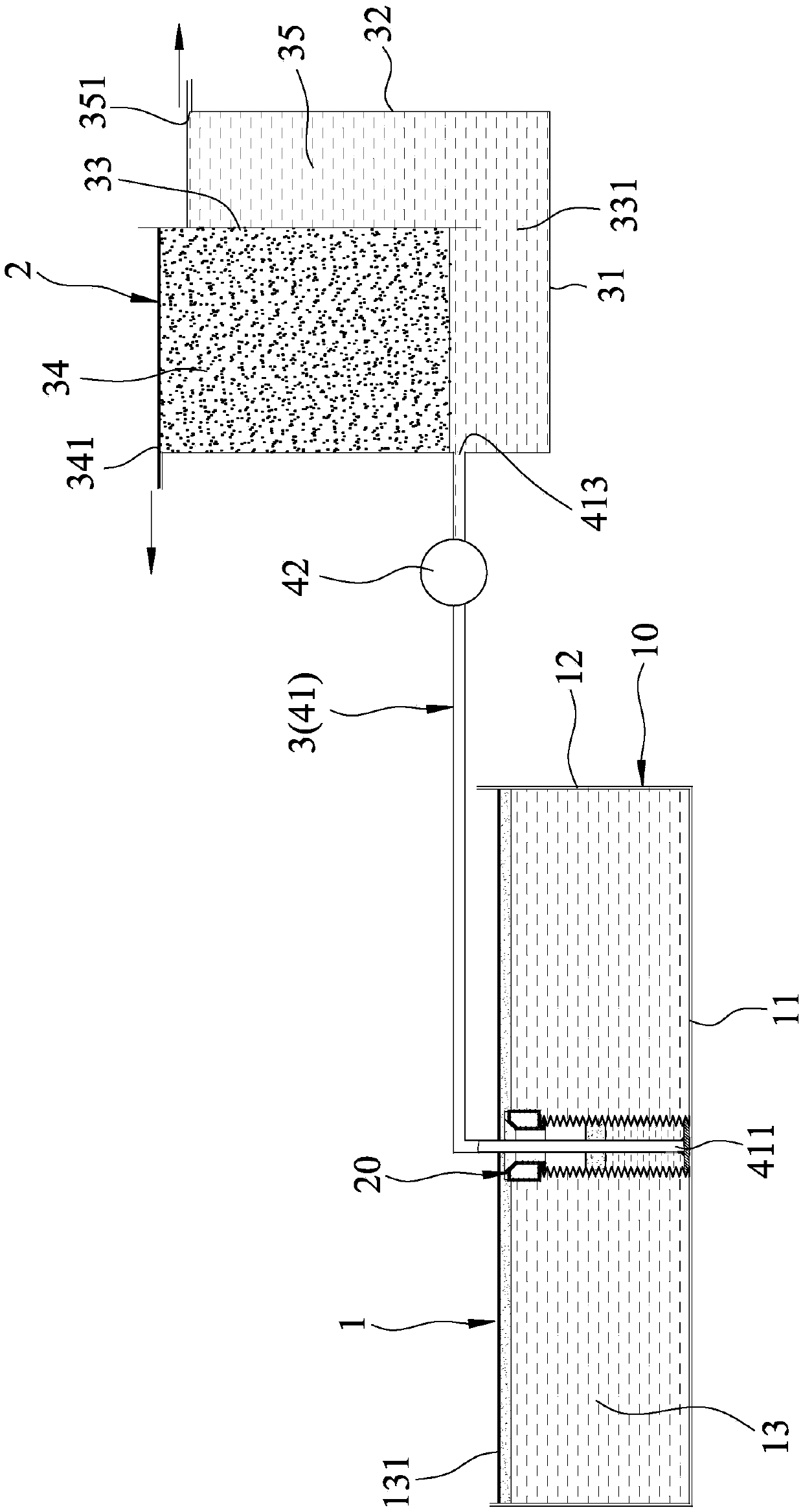
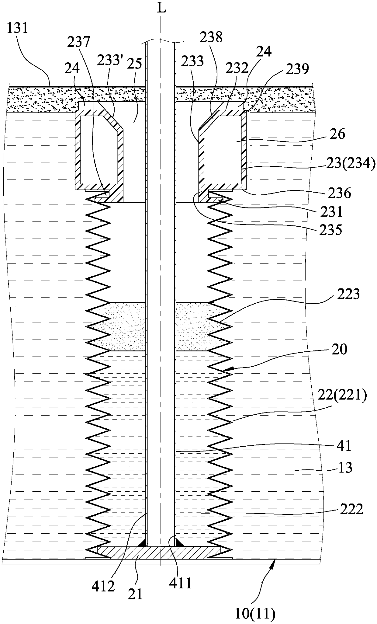
[0018] refer to figure 1 and figure 2 , an embodiment of the two-stage oil-water separator of the present invention includes a first oil-water separator 1 , a second oil-water separator 2 and a pumping unit 3 .

[0019] The first oil-water separation device 1 includes a first liquid storage barrel 10 and a floating unit 20 installed inside the first liquid storage barrel 10 .

[0020] The first liquid storage barrel 10 has a first bottom wall 11, a first peripheral wall 12 extending upward from the peripheral edge of the first bottom wall 11, the first bottom wall 11 and the first peripheral wall 12 are jointly defined A first liquid storage chamber 13 with a notch 131 facing upward.

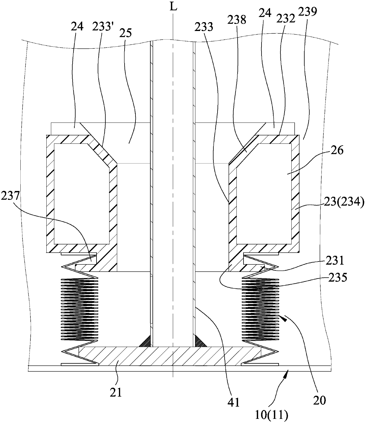
[0021] The floating unit 20 has a fixed seat 21 fixed to the first bottom wall 11, a telescopic tube 22 extending along an axis L and connected to the fixed seat 21...


PUM


Abstract

The invention relates to a two-stage oil-water separator, which comprises a first oil-water separation device, a second oil-water separation device and a pumping unit, wherein the first oil-water separation device comprises a first liquid storage barrel and a floating unit mounted in the first liquid storage barrel, the floating unit is provided with a stretching pipe and a floating body connectedto the stretching pipe, the second oil-water separation device comprises a first accommodating chamber and a second accommodating chamber, the bottoms of the first accommodating chamber and the second accommodating chamber are communicated to each other, the first accommodating chamber is provided with an oil outlet higher than the opening of a first liquid storage chamber, and the second accommodating chamber is provided with a liquid outlet between the oil outlet and a second bottom wall. According to the invention, the first oil-water separation device performs first oil-water separation,and the waste liquid is pumped to the second oil-water separation device by the pumping unit, and is subjected to second oil-water separation, so that the good oil-water separation effect can be achieved.

Description

technical field [0001] The invention relates to an oil-water separation device, in particular to a two-stage oil-water separator. Background technique [0002] For the treatment equipment of the processed cutting waste liquid, such as the patent case of China Taiwan Certificate No. M415739, a floating plate is suspended on the cutting waste liquid. The floating plate has a liquid inlet pipe and a liquid outlet pipe. Pipe for the cutting waste liquid to flow into the floating plate, the liquid outlet pipe is connected with the liquid inlet pipe, and a pump is installed on an oil-water separation device, and the pump is connected to the liquid outlet pipe through a communication pipe And the oil-water separation device, the pump is used to pump the cutting waste liquid into the oil-water separation device. [0003] Although the above-mentioned oil-water separation device can be used to separate the cooling water and cutting oil in the cutting waste liquid, because the suction...

Claims


Application Information

Patent Timeline
Patent Type & Authority Applications(China)
IPC IPC(8): C02F1/40B01D17/12B01D17/028
CPCB01D17/0211B01D17/12C02F1/40C02F2301/08
Inventor 张锦纶
Owner 张 锦 纶
Why Eureka
Try Eureka