High-precision water level control floating ball valve

A technology of water level control and floating ball valve, applied in the direction of lift valve, valve details, valve device, etc., can solve the problems of easy plastic deformation of sealing gasket, difficult processing, fluctuation of steam temperature, etc., and achieve automatic adjustment of water intake and practicality. strong effect

Pending Publication Date: 2020-11-20
刘维
View PDF1 Cites 3 Cited by
  • Summary
  • Abstract
  • Description
  • Claims
  • Application Information

AI Technical Summary

Problems solved by technology

The disadvantages of this intermittent water supply method are: 1. The boiler water temperature will fluctuate periodically, and the steam temperature will also fluctuate accordingly; 2. The stability of the high and low water level electric control system directly affects the reliability of the boiler water supply; 3. In order to To avoid frequent start and stop of the feed water pump, the water capacity of the general boiler drum should be large enough
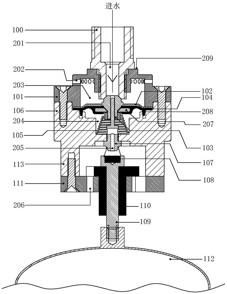
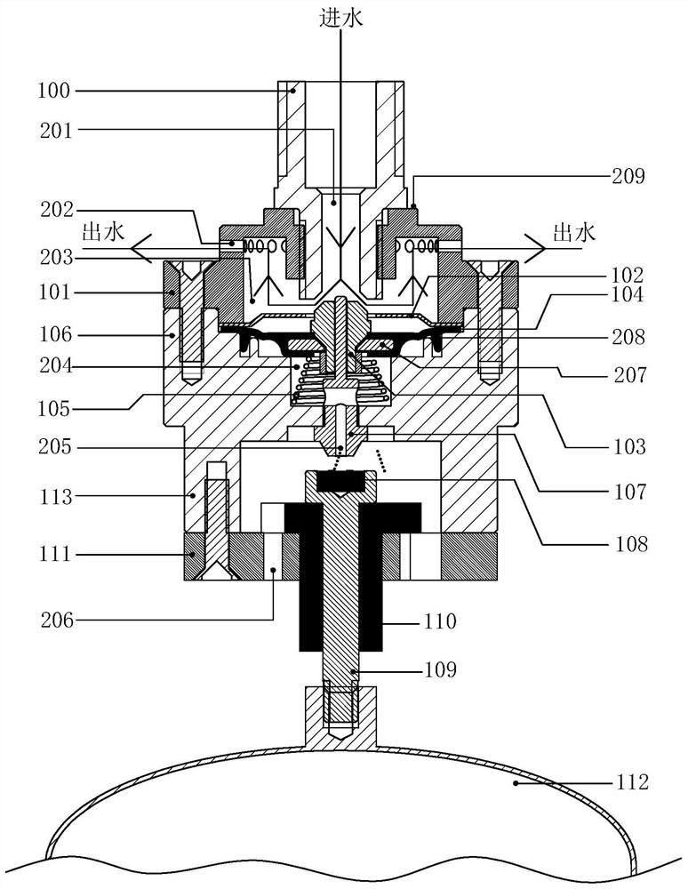
However, the above-mentioned water supply device still has the following deficiencies in the water replenishment of the circulating steam boiler: 1. The threaded connection mode of the upper cavity cover and the lower cavity cover, the connection mode of the water inlet pipe and the upper cavity cover, the silicone material of the sealing rubber pad and the upper part The plane structure will affect the precise positioning of the valve opening, so the water flow is not easy to control. The best working method of the steam boiler is that the feed water flow can follow the change of the output steam flow in real time. Obviously, the above-mentioned device cannot meet the requirements; 2. The pressure bearing capacity of the threaded connection between the cavity sleeve and the lower cavity sleeve is poor, the steam pressure is higher than 0.5Mpa, and the thread is easily damaged; The cavity loses pressure and cannot effectively lock water. When the water pressure is high (about 0.6MP or above), the material of the sealing rubber pad is soft and the plane structure of the upper plane cannot effectively lock water. The sealing rubber pad is in the middle position when it is static. The movement is stretching and deformation, especially when working at high temperature, the sealing rubber pad is easy to be plastically deformed and fails. The upper plane of the center of the sealing rubber pad moves up and down in the center hole of the metal gasket above the sealing rubber pad. In the water state, the water pressure of the working chamber produces an upward thrust on the sealing rubber pad. The higher the water pressure, the greater the thrust, and the sealing rubber pad is easily damaged by the metal gasket; therefore, the upper surface cannot be exposed to water above 0.5MPa. Press down and work for a long time; 4. There are two shortcomings in the integrated design of the bottom cylinder protruding from the bottom center of the lower chamber sleeve: one is that the processing is difficult, and the other is that it is difficult to guarantee the machining accuracy of the bottom cylinder, because the bottom cylinder and the upper plane center hole Therefore, if the bottom cylinder is unqualified, the entire workpiece will be scrapped; 5. The design of the pressure relief hole deviates from the central axis, and the top column is up and down by means of a metal mounting arm (a low-precision sheet metal processing part) There is a problem that the positioning accuracy cannot be guaranteed in the movement. The floating ball deviates from the central axis and makes an arc movement. Under the condition of frequent water level fluctuations, the lateral vibration is large, the movement mechanism is also easy to damage, and the reliability is not high. Therefore, the above-mentioned precision water level control The water supply device is not suitable for water level control and replenishment of steam boilers with high water temperature and high water pressure

Method used


Image

  • High-precision water level control floating ball valve
  • High-precision water level control floating ball valve
  • High-precision water level control floating ball valve

Examples


Embodiment Construction

[0033] The embodiments of the present invention are described in detail below. Examples of the embodiments are shown in the accompanying drawings, in which the same or similar reference numerals indicate the same or similar elements or elements with the same or similar functions. The embodiments described below with reference to the drawings are exemplary, and are only used to explain the present invention, but should not be construed as limiting the present invention.

[0034] In the description of the present invention, it should be understood that the orientation description involved, such as up, down, front, back, left, right, etc., indicates the orientation or positional relationship based on the orientation or positional relationship shown in the drawings, and only In order to facilitate the description of the present invention and simplify the description, it does not indicate or imply that the pointed device or element must have a specific orientation, be constructed and o...


PUM


Abstract

The invention provides a high-precision water level control floating ball valve. The high-precision water level control floating ball valve is characterized in that the high-precision water level control floating ball valve comprises a valve seat and a floating ball; the valve seat is provided with a water inlet cavity, a water locking cavity and a valve sheet between the water inlet cavity and the water locking cavity, wherein the center of the water inlet cavity coincides with the center of the water locking cavity; a water inlet runner is formed at the center position of the water inlet cavity, and the cross sectional area of the water inlet runner is smaller than that of the water locking cavity; a drain opening is formed at the center position of the water locking cavity, a water passing structure is arranged at the center position of the valve sheet, and therefore water with certain pressure in the water inlet runner can enter the water locking cavity through the water passing structure; the floating ball is arranged on the valve seat through a piston rod in a penetrating manner, wherein the axis of the piston rod coincides with the center position of the valve sheet; and inthe process that the piston rod moves, the drain opening can be closed from the outside of the drain opening. According to the floating ball valve, the drain opening can be opened at the extremely small distance that the floating ball descends, and therefore the water inlet runner is in communication to input water; and compared with a traditional floating ball valve structure, the floating ball valve is more suitable for the use condition of a steam furnace, the situation that heating without water happens due to the fact that water is not input in time cannot happen, and practicality is high.

Description

Technical field [0001] The invention relates to the technical field of steam boilers, in particular to a high-precision precision water level control float valve suitable for water supply of a circulating steam boiler. Background technique [0002] The steam boiler refers to the heat energy conversion equipment that produces steam. In the process of producing steam, the boiler must be supplemented with water in real time on demand to avoid water shortage and dry burning in the furnace and damage the boiler. Among them, the circulating steam boiler is also called a drum boiler. The drum generally has two functions, one is steam-water separation, and the other is water supply. The high and low water level detection is set in the steam drum, and the water supply is controlled by the high and low water level. The shortcomings of this intermittent water supplement method are: 1. The boiler water temperature will fluctuate periodically, and the steam temperature will also fluctuate ac...

Claims


Application Information

Patent Timeline
IPC IPC(8): F16K1/00F16K1/32F16K1/36F16K1/46F16K27/02F16K31/24
CPCF16K1/00F16K1/32F16K1/36F16K1/46F16K27/02F16K31/24
Inventor 刘维
Owner 刘维
Why Eureka
Try Eureka