Check patentability & draft patents in minutes with Patsnap Eureka AI!

Signal sending method and device

A technology for sending signals and data signals, applied in the field of communications, it can solve the problems of time asynchrony, transmitter signal interference, etc., and achieve the effect of strong resistance to measurement errors and elimination of detection delays

Active Publication Date: 2020-01-07
HUAWEI TECH CO LTD
View PDF5 Cites 3 Cited by
  • Summary
  • Abstract
  • Description
  • Claims
  • Application Information

AI Technical Summary

Problems solved by technology

[0005] This application provides a method and device for sending signals, which are used to solve the problem of signal interference between transmitters caused by time asynchrony when multiple transmitters perform joint transmission

Method used


Image

  • Signal sending method and device
  • Signal sending method and device
  • Signal sending method and device

Examples


Embodiment Construction

[0056] The embodiments of the present application will be further described in detail below in conjunction with the accompanying drawings.

[0057] Before the detailed explanation of the signal sending method provided by the embodiment of the present application, the implementation environment involved in the embodiment of the present application will be introduced first.

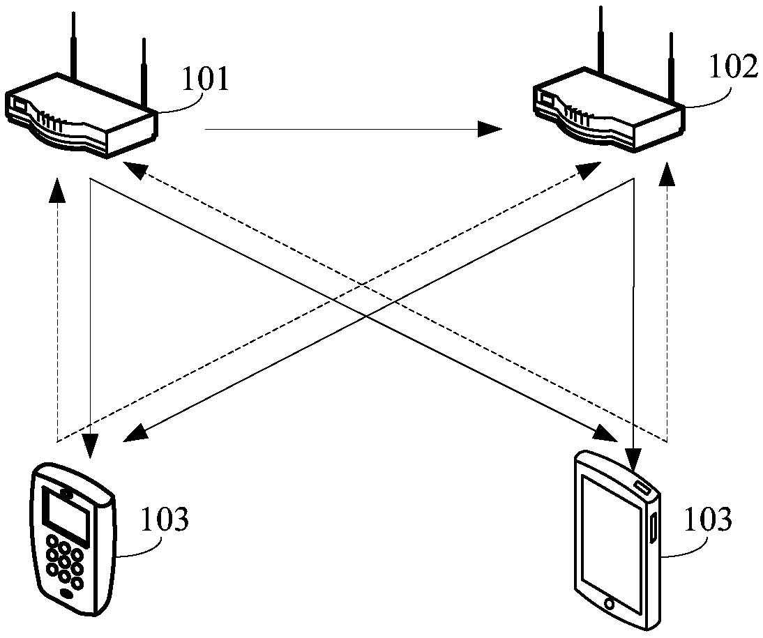
[0058] figure 1 is a schematic diagram of the implementation environment applicable to the signal sending method provided by the embodiment of the present application, such as figure 1 As shown, the implementation environment may include a master transmitter 101 , a slave transmitter 102 and a receiver 103 . Wherein, the master transmitter 101 and the slave transmitter 102 can communicate through a wireless network, the master transmitter 101 and the receiver 103 can communicate through a wireless network, and the slave transmitter 102 and the receiver 103 can also communicate through a wireless network. ...


PUM


Abstract

The invention discloses a signal sending method and device, and belongs to the technical field of communication. The method comprises the steps of generating a first data signal based on channel stateinformation, receiving a second data signal sent by a main transmitter, determining the phase of the second data signal, determining the number of sampling points based on the phase of a first measurement signal sent by the main transmitter and the phase of the second data signal, and sending the first data signal based on the number of sampling points. Namely, the phase of the second data signaltransmitted by the main transmitter is compared with the phase of the first measurement signal transmitted by the main transmitter during channel measurement. The number of sampling points with the phase difference obtained through conversion is determined through the phase difference of the two phases, and the first data signal is sent based on the number of sampling points, so that the detection time delay in the joint sending process of the master transmitter and the slave transmitter can be eliminated, and the time synchronization of the master transmitter and the slave transmitter is realized.

Description

technical field [0001] The present application relates to the technical field of communications, and in particular to a method and device for sending signals. Background technique [0002] A multiple input multiple output (Multiple Input Multiple Output, MIMO) technology has gradually become a mainstream signal transmission technology in a wireless communication system. The so-called MIMO technology means that the transmitter includes multiple antennas, and when transmitting signals, the transmitter can send signals to multiple receivers at the same time and on the same frequency. Moreover, considering the problem of signal interference, the distance between every two adjacent antennas among the multiple antennas of the transmitter needs to be greater than a certain value. Based on this, due to the limitation of the equipment size of the transmitter, the number of antennas included in the transmitter will be limited, that is, when transmitting signals through the MIMO techn...

Claims


Application Information

Patent Timeline
IPC IPC(8): H04J3/06H04L7/02H04W56/00
CPCH04J3/0682H04L7/02H04W56/0055H04B7/024H04J3/0617H04J3/14H04W56/0035H04B7/0619H04B17/309
Inventor 杨博顾巍袁方超陈鹏
Owner HUAWEI TECH CO LTD
Features
  • R&D
  • Intellectual Property
  • Life Sciences
  • Materials
  • Tech Scout
  • Unparalleled Data Quality
  • Higher Quality Content
  • 60% Fewer Hallucinations
Learn More