Steel structural component convenient to disassemble and assemble

A technology of steel structures and components, which is applied in the direction of building construction and construction, and can solve problems such as difficult disassembly and assembly of beams

Inactive Publication Date: 2020-01-10
江苏双鹏钢结构工程有限公司
View PDF12 Cites 9 Cited by
  • Summary
  • Abstract
  • Description
  • Claims
  • Application Information

AI Technical Summary

Problems solved by technology

[0003] However, traditional steel structural members generally fix the beams on the pillars by bolting, welding or riveting. Therefore, this type of steel structural members has the problem that it is not easy to disassemble the beams.

Method used


Image

  • Steel structural component convenient to disassemble and assemble
  • Steel structural component convenient to disassemble and assemble
  • Steel structural component convenient to disassemble and assemble

Examples


Embodiment 1

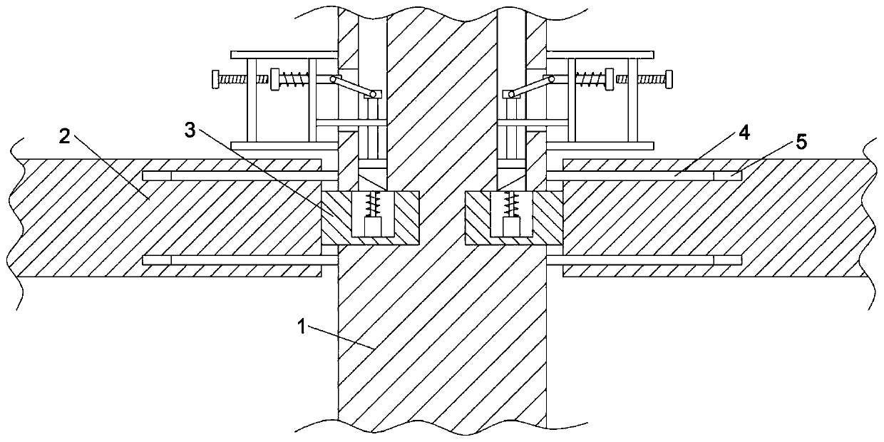
[0026] Refer to attached Figure 1-5 , this embodiment provides a steel structural member that is easy to assemble and disassemble, including a pillar 1 and two sets of symmetrical beams 2, and the pillars 1 and the beams 2 are made of steel. In addition, the pillar 1 is provided with two sets of slots 11 corresponding to the crossbeam 2, and a positioning assembly for positioning the crossbeam 2 is provided between the pillar 1 and the crossbeam 2. There is a block 3 matching with the slot 11, the block 3 is provided with a limiting assembly for limiting the block 3, and the pillar 1 is also provided with a mounting hole 12, the The installation hole 12 communicates with the card slot 11, and the installation hole 12 is provided with a release assembly for releasing the limit assembly to the block 3; when the block 3 is inserted into the card slot 11 , said limit assembly automatically clamps the clamping block 3 in the clamping slot 11 .

[0027] Specifically, the position...

Embodiment 2

[0033] Refer to attached Figure 6 , this embodiment is improved on the basis of embodiment 1, specifically, the second fixed block 31 is fixed on the beam 2, and the second fixed block 31 is rotatably connected with one end of the telescopic rod 30, The other end of the telescopic rod 30 is rotatably connected to the second connecting block 29, the second connecting block 29 is fixed with a limit rod 28, the pillar 1 is fixed with a first fixed block 26, and the The first fixing block 26 is provided with a limiting hole 27 matched with the limiting rod 28 . By rotating and elongating the telescopic rod 30 , the limit rod 28 can be inserted into the limit hole 27 , so as to play the role of auxiliary support and fixation of the beam 2 .

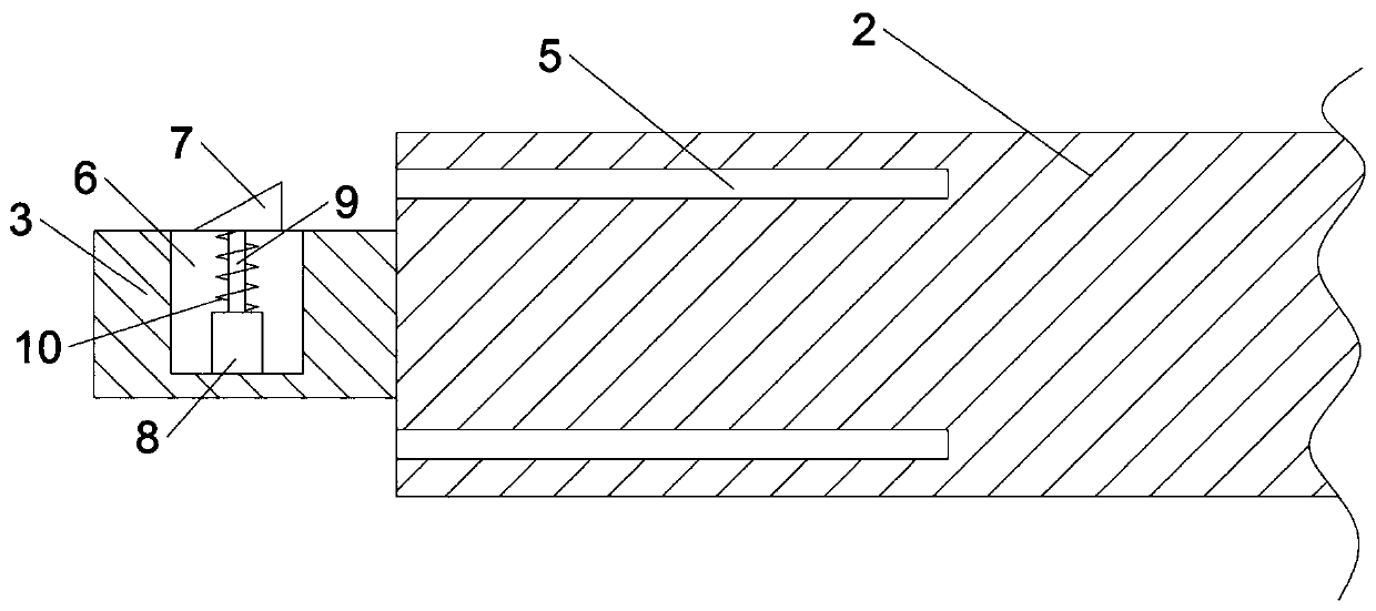
[0034] To sum up, the steel structural member provided by the embodiment of the present invention is provided with a positioning assembly with a positioning rod 4 and a positioning hole 5 between the pillar 1 and the crossbeam 2, and the cla...


PUM


Abstract

The invention discloses a steel structure component convenient to disassemble and assemble, and belongs to the field of steel structures. The steel structural component comprises a support column anda plurality of sets of beams. A plurality of sets of clamping grooves corresponding to the beams are formed in the support column. Positioning assemblies are arranged between the support column and the beams. Clamping blocks matched with the clamping grooves are arranged on the beams. Limiting assemblies are arranged on the clamping blocks. Mounting holes are formed in the support column. The mounting holes are communicated with the clamping grooves. Releasing assemblies are arranged in the mounting holes. According to the steel structure component convenient to disassemble and assemble, by arranging the limiting assemblies on the clamping blocks, the clamping blocks can be inserted into the clamping grooves, and automatic limiting of the clamping blocks is achieved, so that the beams canbe conveniently and fixedly mounted on the support column. In addition, the releasing assemblies are arranged in the mounting holes, and the limiting of the clamping blocks can be released by the releasing assemblies, so that the clamping blocks can be conveniently pulled out from the clamping grooves, and the disassembly operation of the beams is achieved.

Description

technical field [0001] The invention relates to the field of steel structures, in particular to a steel structure component that is easy to assemble and disassemble. Background technique [0002] Steel structural components include steel structural frames, supports, etc., which are generally composed of pillars and several sets of beams. Since the component uses steel as the material of the pillars and beams, it can greatly improve the service life of the component. [0003] However, traditional steel structural members generally fixedly install the beams on the pillars by bolting, welding or riveting. Therefore, this type of steel structural members has the problem that it is not easy to disassemble the beams. Contents of the invention [0004] The object of the present invention is to provide a steel structural component that is easy to assemble and disassemble, so as to solve the problems raised in the above-mentioned background technology. [0005] To achieve the abov...

Claims


Application Information

Patent Timeline
Patent Type & Authority Applications(China)
IPC IPC(8): E04B1/24E04B1/58
CPCE04B1/24E04B1/2403
Inventor 韩彭城
Owner 江苏双鹏钢结构工程有限公司
Why Eureka
Try Eureka