Electromagnetic control lock for cabinet

An electromagnetic control and cabinet technology, applied in the field of cabinet security, can solve the problems of uncontrollable mechanical keys, easy to be copied, easy to be hidden, etc., to achieve the effect of improving anti-theft security and preventing unlocking

Inactive Publication Date: 2020-01-10
FUYANG WANRUI ELECTRONICS LOCKS CO LTD
View PDF0 Cites 2 Cited by
  • Summary
  • Abstract
  • Description
  • Claims
  • Application Information

AI Technical Summary

Problems solved by technology

[0002] Generally, the mortise type electric control anti-theft lock adopts a spare mechanical lock core and an electric control mechanism to realize the opening or locking of the lock tongue, and these two opening or locking methods are independently completed, that is, the spare mechanical key can be used. The lock can be opened and closed independently without the interference of the electric control mechanism, and the same is true for the electric control mechanism; the traditional electric control lock structure in which the mechanical opening and closing tools and the electric control opening and closing tools coexist is not suitable for public places such as The anti-theft door of the computer room and base

Method used


Image

  • Electromagnetic control lock for cabinet
  • Electromagnetic control lock for cabinet
  • Electromagnetic control lock for cabinet

Examples


Embodiment Construction

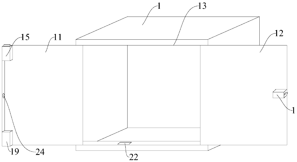
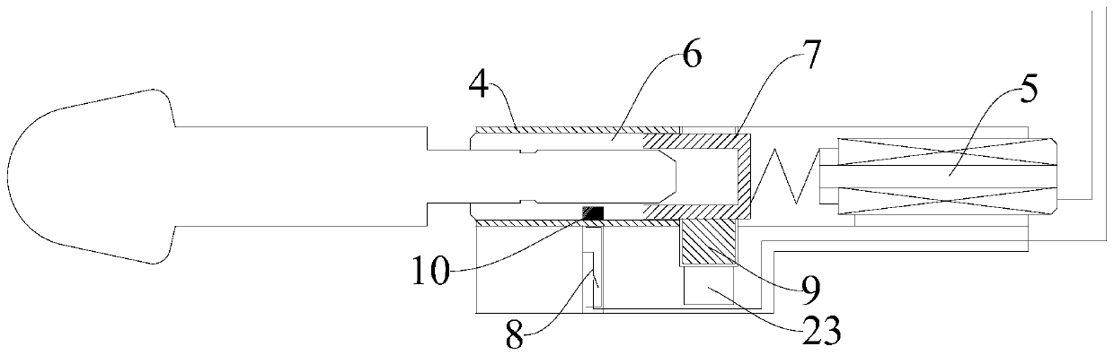
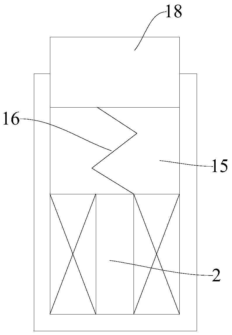
[0017] The present invention is described in further detail now in conjunction with accompanying drawing. These drawings are all simplified schematic diagrams, which only illustrate the basic structure of the present invention in a schematic manner, so they only show the configurations related to the present invention.

[0018] figure 1 and figure 2 The shown electromagnetic control lock for cabinets includes a main cabinet 1, a top solenoid valve 2, a bottom solenoid valve 3, a main lock body 4, a built-in solenoid valve 5 installed inside the main lock body 4, and a The lock core shaft 6 inside the main lock body 4, the clutch slider 7 installed inside the main lock body 4, the normally closed magnetic control switch 8 installed on the outside of the main lock body 4 for controlling the built-in solenoid valve 5, the built-in solenoid valve 5 and the clutch slider 7 are connected by an extruding spring, which is convenient to control the elastic reset of the clutch slider...


PUM


Abstract

The invention relates to the technical field of cabinet safety, in particular to an electromagnetic control lock for a cabinet. The electromagnetic control lock for the cabinet is used for fixedly locking a left overturning cabinet door and the inner side surface of a front operation port through an upper electromagnetic elastic locking mechanism and a lower electromagnetic elastic locking mechanism, and an internal lock body composed of a main lock body, an internally-arranged solenoid valve, a lock cylinder shaft, a clutch sliding block and a normally closed magnetic control switch is fixedto the inner side surface of a right overturning cabinet door through bolts. Magnetic steel inside the internal lock body controls the normally closed magnetic control switch to open and close, so that the internally-arranged solenoid valve is opened and closed to control the connection state of the clutch sliding block and a lock cylinder cam, a mechanical key is prevented from unlocking under apower-on state, and the security of theft prevention is improved.

Description

technical field [0001] The invention relates to the technical field of cabinet safety, in particular to an electromagnetic control lock for a cabinet. Background technique [0002] Generally, the mortise type electric control anti-theft lock adopts a spare mechanical lock core and an electric control mechanism to realize the opening or locking of the lock tongue, and these two opening or locking methods are independently completed, that is, the spare mechanical key can be used. The lock can be opened and closed independently without the interference of the electric control mechanism, and the same is true for the electric control mechanism; the traditional electric control lock structure in which the mechanical opening and closing tools and the electric control opening and closing tools coexist is not suitable for public places such as The anti-theft door of the computer room and base station of the iron tower company; the reason is that the normal and legal means of opening ...

Claims


Application Information

Patent Timeline
IPC IPC(8): E05B65/52E05B47/02E05B47/06E05B63/14E05B15/00
CPCE05B15/00E05B47/0002E05B47/026E05B47/0603E05B63/143E05B65/52E05B65/523
Inventor 林卫中
Owner FUYANG WANRUI ELECTRONICS LOCKS CO LTD
Why Eureka
Try Eureka