Track tracking optimization method under radar far-near alternative ranging mode

A track tracking and optimization method technology, applied in the field of radar, can solve the problems of unstable driving state, not smooth enough track, target tracking failure, etc., and achieve the effect of improving continuity and smoothing effect of filtering

Active Publication Date: 2020-01-10
NANJING DESAY SV AUTOMOTIVE CO LTD
View PDF9 Cites 3 Cited by
  • Summary
  • Abstract
  • Description
  • Claims
  • Application Information

AI Technical Summary

Problems solved by technology

[0002] Vehicle-mounted radars set corresponding frame structures and transmitting antennas according to different ranging requirements, resulting in the measurement accuracy of point traces obtained in the near ranging mode (hereinafter referred to as 'near standard') and the far ranging mode (hereinafter referred to as 'far standard'). The difference is that the measurement accuracy of the radial distance of the near standard target is higher than that of the far standard, while the measurement accuracy of the near standard target angle is lower than that of the far standard
Therefore, when a single near system is used for track tracking, it is easy to lose point track information at a long distance (such as beyond 120m), resulting in failure to match the point track with the track; (For example, within 20m) the accuracy of the point track information is low, which leads to the wrong matching between the point track and the tr

Method used


Image

  • Track tracking optimization method under radar far-near alternative ranging mode
  • Track tracking optimization method under radar far-near alternative ranging mode

Examples


Embodiment 1

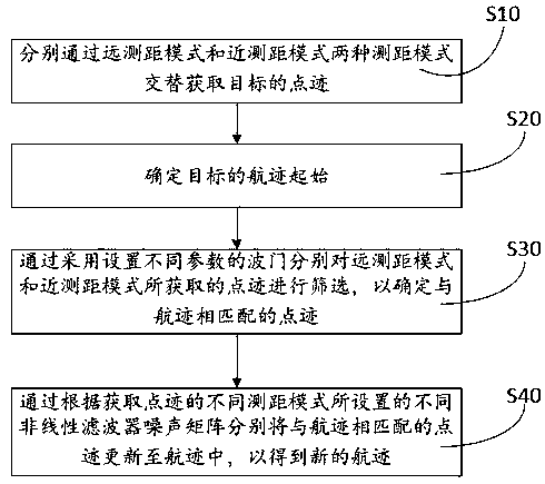
[0047] An optimization method for track tracking in the radar alternate distance measurement mode, such as figure 1 As shown, including the following steps:

[0048] S10. Obtain the point trace of the target alternately through two ranging modes, the long range mode and the short range mode.

[0049] This step is specifically as follows: two ranging modes are set for the vehicle-mounted radar, a long range measurement mode and a short range measurement mode, and the target traces are obtained alternately through the two range measurement modes of the long range measurement mode and the short range measurement mode respectively.

[0050] S20. Determine the start of the target's trajectory through the continuity of the continuously acquired multi-frame point traces.

[0051] This step is specifically: continuously acquiring multi-frame point traces, judging the continuity of the acquired multi-frame point traces, and starting the target track when it is confirmed that the acquired multi-...


PUM


Abstract

The invention relates to a track tracking optimization method under a radar far-near alternative ranging mode. The method comprises the following steps of alternately acquiring the trace points of a target through a long ranging mode and a near ranging mode; determining the track start of the target through the continuity of continuously acquired multi-frame track points; screening the track points acquired by the long ranging mode and the near ranging mode by adopting gates with different parameters to determine the track points matched with the flight track; and updating the track points matched with the flight tracks into the flight tracks through different nonlinear filter noise matrixes set according to different distance measuring modes for obtaining the point tracks, thereby obtaining new flight tracks. Through the method disclosed by the invention, the matching continuity of track points and flight tracks is improved by adopting the self-adaptive sector wave gate for matching,and the flight tracks are optimized by arranging different nonlinear filter noise matrixes through different ranging modes for acquiring track points, thereby improving the filtering smoothing effectof the flight tracks and the estimation precision of the motion state of the detected target.

Description

Technical field [0001] The invention relates to the technical field of radars, in particular to a method for tracking and optimizing a track in a radar distance alternate range measurement mode. Background technique [0002] The vehicle-mounted radar sets up the corresponding frame structure and transmitting antenna according to different ranging requirements, resulting in the short-range measurement mode (hereinafter referred to as the "near mode") and the long ranging mode (hereinafter referred to as the "far mode"). The difference, for example, the measurement accuracy of the radial distance of the short-mode target is higher than that of the far mode, and the measurement accuracy of the short-mode target angle is lower than that of the far mode. Therefore, when a single near system is used for track tracking, it is easy to lose track information at a long distance (such as beyond 120m), resulting in the failure of the matching of the point track and the track; (For example, ...

Claims


Application Information

Patent Timeline
IPC IPC(8): G01S13/72
CPCG01S13/723Y02T10/40
Inventor 周琼峰唐培培季丹
Owner NANJING DESAY SV AUTOMOTIVE CO LTD
Why Eureka
Try Eureka