Rainproof and windproof isolation switch mechanism convenient for fixation

A technology of isolating switch and protective body, which is applied in the field of isolating switch mechanism, which can solve the problems of difficult to install and install the isolating switch, no firmness, corrosion and fixation of the fixing mechanism, etc., so as to improve the reliability of power supply, facilitate rainproof and windproof, and avoid wind blowing rain effect

Inactive Publication Date: 2020-01-10
STATE GRID SHANDONG ELECTRIC POWER +1
View PDF9 Cites 0 Cited by
  • Summary
  • Abstract
  • Description
  • Claims
  • Application Information

AI Technical Summary

Problems solved by technology

[0002] After the existing isolating switch is installed outdoors, the isolating switch made of porcelain material is easy to crack after being exposed to wind, rain and sun, and the insulation degree of the isolating switch will be reduced.
Therefore, when the isolating switch is operated, arcing will occur between the isolating switches. Due to the cracking of the isolating switch made of porcelain material, the insulation degree will be reduced. It cannot cut off the power connection by itself, and trips the line, thereby affecting the reliability of power supply
[0003] At present, it is difficult to fix the isolating switch in some outdoor occasions, such as on utility poles, or on some iron towers, or on some cross-arms, it is difficult to firmly fix the isolating switch
Although in some areas, the isolating switch is fixed to the pole by binding or bolts, or on some iron towers, or on some cross-arms, but due to wind, rain and sun, the fixing mechanism is corroded or the fixing is no longer firm, resulting in isolation The switch falls off, or the fall affects the reliability of power supply

Method used


Image

  • Rainproof and windproof isolation switch mechanism convenient for fixation
  • Rainproof and windproof isolation switch mechanism convenient for fixation
  • Rainproof and windproof isolation switch mechanism convenient for fixation

Examples


Embodiment Construction

[0030] Furthermore, the described features, structures or characteristics may be combined in one or more embodiments in any suitable manner. In the following description, many specific details are provided to give a sufficient understanding of the embodiments of the present invention. However, those skilled in the art will realize that the technical solutions of the present invention can be practiced without one or more of the specific details, or other methods, components, devices, steps, etc. can be used. In other cases, well-known methods, devices, implementations, or operations are not shown or described in detail to avoid obscuring aspects of the present invention.

[0031] It should be understood that when an element or layer is referred to as being "on" another element or layer and is "connected" or "coupled" to another element or layer, it may be directly on the other element or layer and be directly connected Or coupled to the other element or layer, there may also be i...


PUM


Abstract

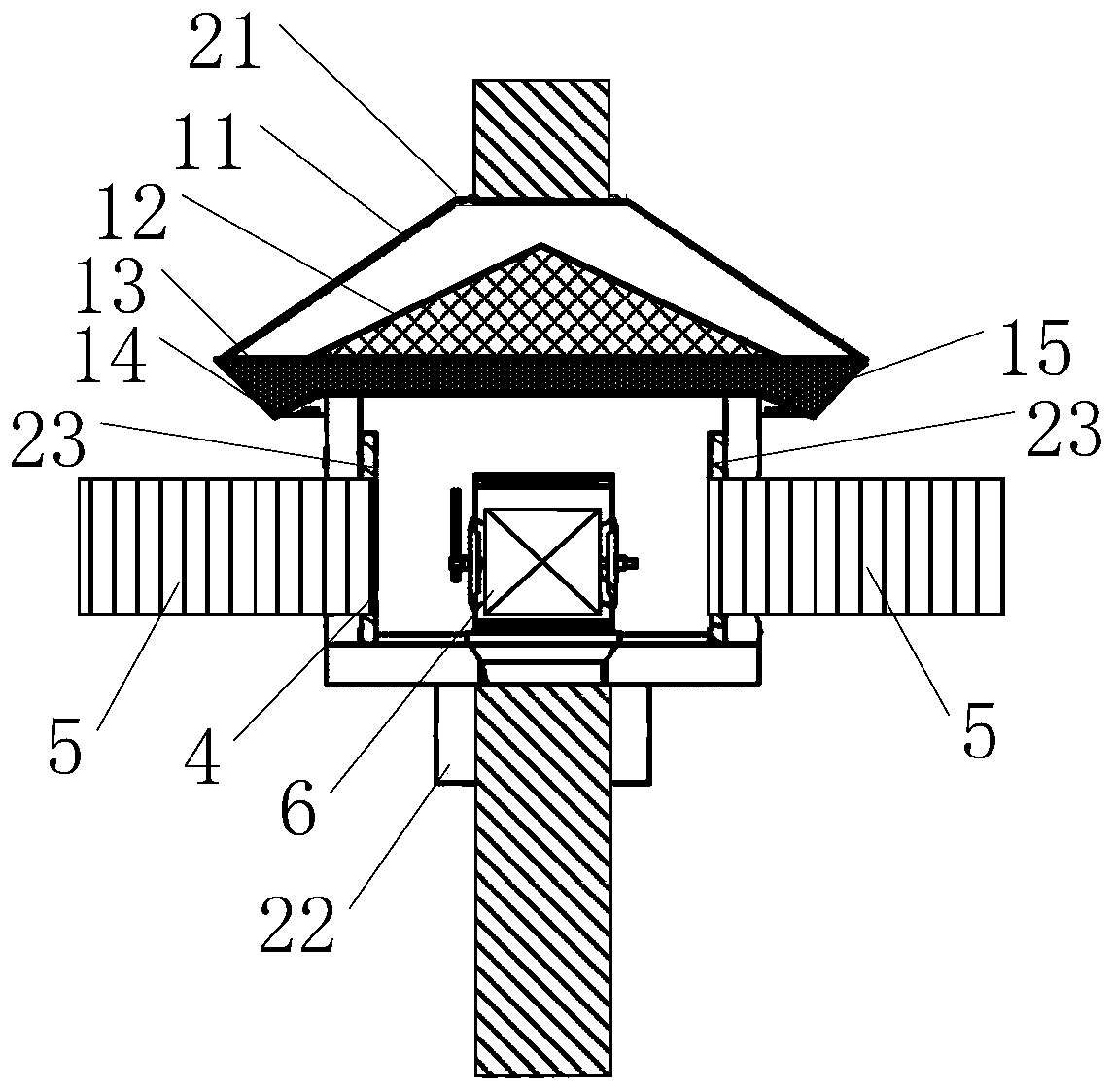
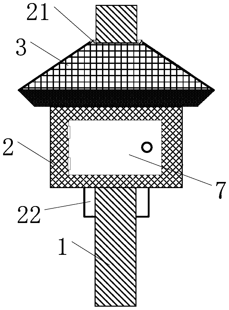
The invention provides a rainproof and windproof isolation switch mechanism convenient for fixation. A vertical rod is provided with a protection body, and an upper part of the protection body is provided with an upper cover. An upper through hole is arranged in the upper cover. The vertical rod successively penetrates through a bottom of the protection body and passes through the upper cover through the upper through hole. A horizontal through hole and an opening and closing door are arranged on a side wall of the protection body. A horizontal rod penetrates through the protection body through the horizontal through hole. An isolation switch is arranged on a bottom plate of the protection body. By using the mechanism, the isolation switch can be installed in the protection body, long-timewind blowing and rain drenching of the isolation switch are avoided, an isolation plate can be used for isolating inter-phase arc discharge, accidents are avoided, and power supply reliability is improved. And a problem that the isolation switch cannot cut off power supply connection due to cracking of the isolation switch made of a porcelain material and insulation degree reduction is avoided.

Description

Technical field [0001] The present invention relates to the technical field of isolation switch protection, in particular to an isolation switch mechanism that is convenient for fixing, rainproof and windproof. Background technique [0002] After the existing isolating switch is installed outdoors, the isolating switch made of porcelain material is prone to cracking after wind, rain, and sun, and the insulation degree of the isolating switch is reduced. Therefore, when the isolating switch is operated, an arc will occur between the isolating switches. Due to the cracking of the isolating switch made of ceramic material, the degree of insulation is reduced. When the arc is drawn, the arc short circuit is caused, and the two-phase short circuit of the isolating switch makes the isolating switch The power connection cannot be cut off by itself, and the line is tripped, which affects the reliability of power supply. [0003] At present, it is difficult to fix the isolation switch in s...

Claims


Application Information

Patent Timeline
Patent Type & Authority Applications(China)
IPC IPC(8): H01H9/02H01H9/04H01H9/30H01H9/34H01H9/54H01H33/02H01H33/04H01H33/08H01H33/53H01H33/59G08C17/02
CPCG08C17/02H01H9/02H01H9/0271H01H9/04H01H9/30H01H9/34H01H9/54H01H33/027H01H33/04H01H33/08H01H33/53H01H33/59
Inventor 刘新勇亓恒杰刘跃文公鑫张鹏史修德王道荣李峰王云涛秦呈波王帅刘超郑金升王本立亓娜
Owner STATE GRID SHANDONG ELECTRIC POWER
Why Eureka
Try Eureka