AI technical title is built by PatSnap AI team. It summarizes the technical point description of the patent document.
A newborn and combination technology, applied in the medical field, can solve problems such as the single function of the newborn rescue station
Inactive Publication Date: 2020-01-14
商丘市第一人民医院
View PDF5 Cites 3 Cited by
Summary
Abstract
Description
Claims
Application Information
AI Technical Summary
This helps you quickly interpret patents by identifying the three key elements:
Problems solved by technology
Method used
Benefits of technology
Problems solved by technology
[0002] The neonatal rescue table is a commonly used medical equipment, but the general neonatal rescue table has a single function
Method used
Image
Click on the blue label to locate the original text in one second.
Reading with bidirectional positioning of images and text.
Examples
specific Embodiment approach 1
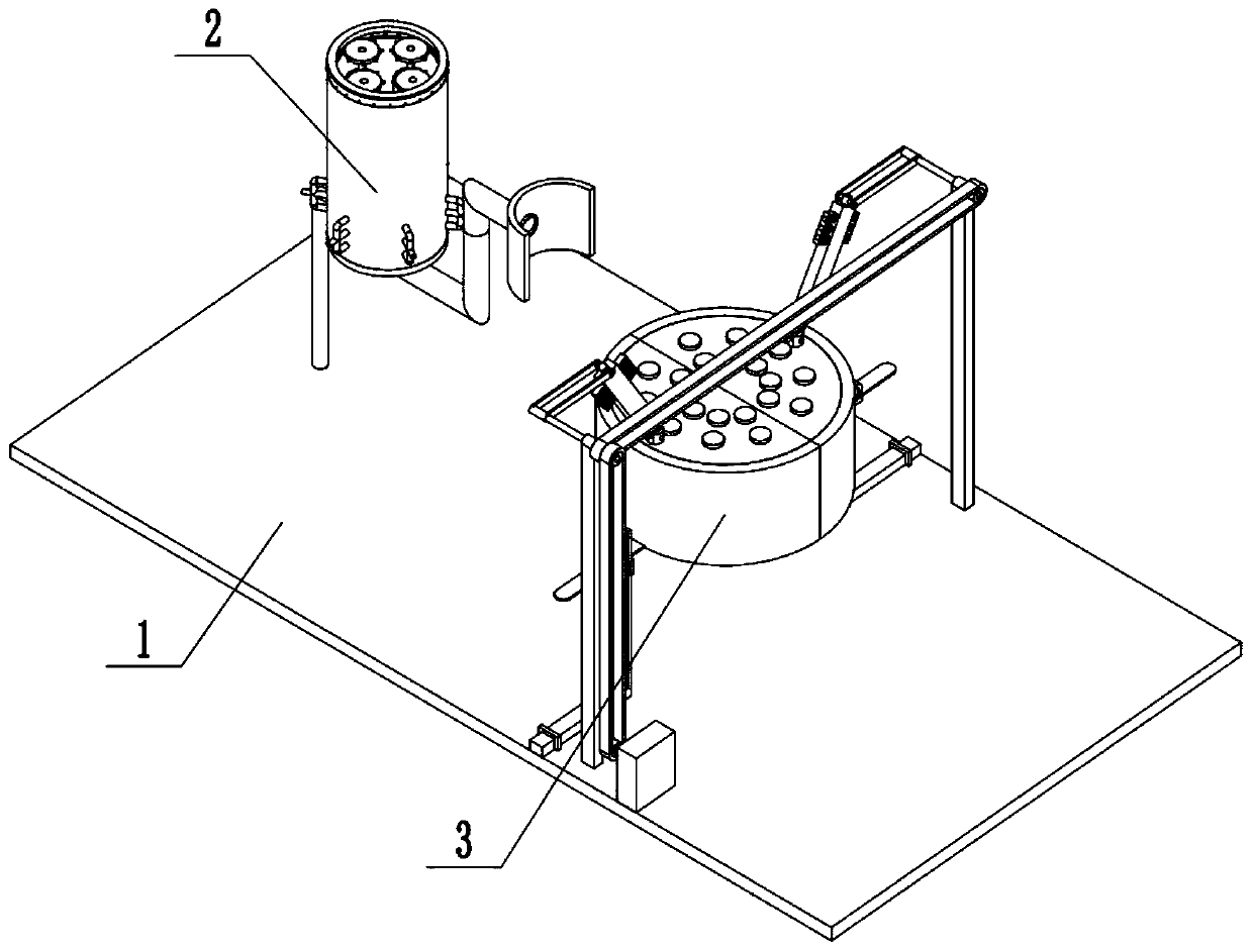
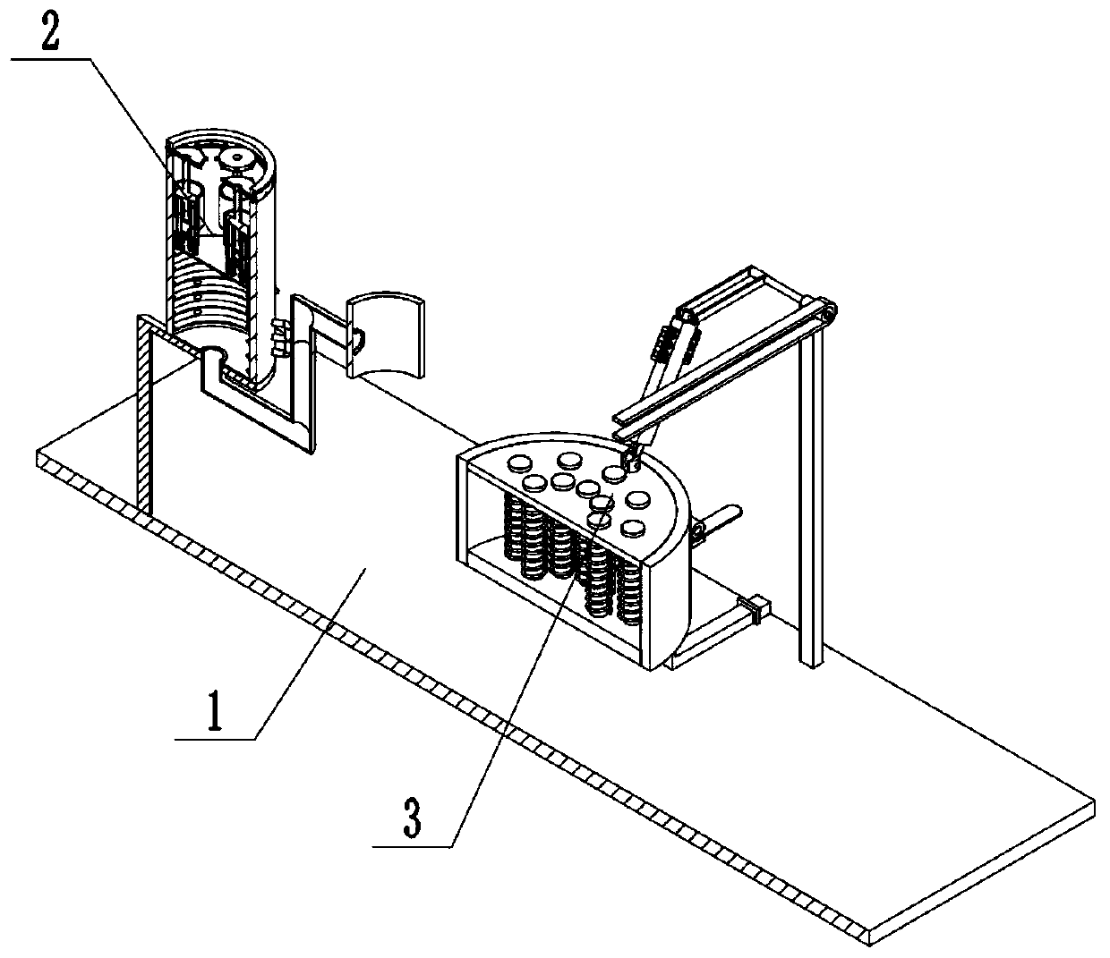
[0040] Combine below Figure 1-23 Describe this embodiment, a newborn rescue platform, including a base plate assembly 1, a breathing assembly 2, and a cardiopulmonary resuscitation assembly 3, characterized in that: the breathing assembly 2 is connected to the base plate assembly 1, and the cardiopulmonary resuscitation assembly The body 3 is connected with the base plate assembly 1 .
specific Embodiment approach 2
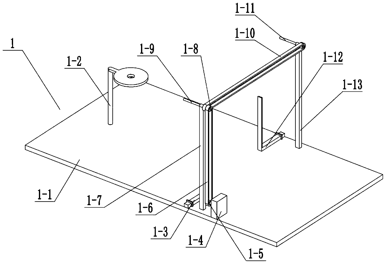
[0042] Combine below Figure 1-23 Describe this embodiment, this embodiment will further explain Embodiment 1, the base plate assembly 1 includes a base plate body 1-1, a bracket 1-2, a rectangular slider 1-3, an input motor 1-4, an input belt Wheel 1-5, connecting belt one 1-6, bracket two 1-7, transmission pulley one 1-8, driving shaft one 1-9, driving belt 1-10, driving shaft two 1-11, rectangular sliding bar two 1 -12, bracket three 1-13, bracket one 1-2 is connected with base plate body 1-1, rectangular slide bar one 1-3 is connected with base plate body 1-1, input motor 1-4 is connected with base plate body 1-1 The input pulley 1-5 is connected with the input motor 1-4, the connecting belt one 1-6 is connected with the input pulley 1-5, the bracket two 1-7 is connected with the bottom plate body 1-1, the bracket three 1-13 is connected with base plate body 1-1, driving shaft one 1-9 is connected with bracket two 1-7, transmission pulley one 1-8 is connected with driving...
specific Embodiment approach 3
[0044] Combine below Figure 1-23 This embodiment will be described. This embodiment will further illustrate the first embodiment. The breathing assembly 2 includes an outer tube 2-1, a connecting tube 2-2, a breathing mask 2-3, an upper limit sleeve 2-4, a communication tube Hole 1 2-5, transmission disc 2-6, inner end air bag 2-7, cut surface arc rod 2-8, outer end casing 2-9, ventilation pipe 2-10, inner end through hole 2-11, card Rod 2-12, card rod slide bar 2-13, inner end push spring 2-14, compression rod 2-15, compression spring 2-16, lower end plate 2-17, lower end push sleeve 2-18, inner end push Spring A2-19, one-way ventilation valve casing 2-20, vent hole 2-21, inner end sliding ball 2-22, inner end cylindrical sliding rod 2-23, inner end cylindrical sleeve spring 2-24, arc Shaped vent hole 2-25, inner cavity 2-26, side wall rectangular through hole 2-27, ring drive rod 2-28, inner wall chute 2-29, inner end clip 2-30, inner end clip push spring 2- 31. The conne...
PUM
Abstract
The invention relates to the field of medical treatment, in particular to a newborn rescue table which can blow air into the body of a newborn through a breathingassembly to complete the breathing process in newborn rescue. The cardiopulmonary resuscitation process in neonatal rescue can be completed through a cardiopulmonary resuscitationassembly; the use position in newborn rescue can be adjusted; the newborn rescue table comprises a bottom plate assembly, the breathing assembly and the cardiopulmonary resuscitation assembly, the use position of the cardiopulmonary resuscitation assembly is adjusted according to the actual condition; a pressing outer frame is subjected to manual pulling, the pressing outer frame drives a side wall rack to move between an adjusting gear I and the matched outer frame; the transverse use position of the cardio-pulmonary resuscitation assembly is adjusted, meanwhile, the pressing outer frame is vertically pulled along a first rectangular sliding rod Iin a sliding mode, the distance between the cardio-pulmonary resuscitation assembly and the bottom plate body is changed under the action of the first rectangular sliding rod I and a second adjustinggear, and then the use height of the cardio-pulmonary resuscitation assembly is adjusted.
Description
technical field [0001] The invention relates to the medical field, in particular to a newborn rescue platform. Background technique [0002] The neonatal rescue table is a commonly used medical equipment, but the general neonatal rescue table has a single function. Contents of the invention [0003] The purpose of the present invention is to provide a newborn rescue platform, which can blow air into the baby's body through the breathing assembly to complete the breathing process in the rescue of the newborn; Resuscitation process; can adjust the position of use in neonatal rescue. [0004] The purpose of the present invention is achieved through the following technical solutions: [0005] A newborn rescue platform, including a base plate assembly, a breathing assembly, and a cardiopulmonary resuscitation assembly, characterized in that: the breathing assembly is connected to the base plate assembly, and the cardiopulmonary resuscitation assembly is connected to the base ...
Claims
Application Information
Patent Timeline
Application Date:The date an application was filed.
Publication Date:The date a patent or application was officially published.
First Publication Date:The earliest publication date of a patent with the same application number.
Issue Date:Publication date of the patent grant document.
PCT Entry Date:The Entry date of PCT National Phase.
Estimated Expiry Date:The statutory expiry date of a patent right according to the Patent Law, and it is the longest term of protection that the patent right can achieve without the termination of the patent right due to other reasons(Term extension factor has been taken into account ).
Invalid Date:Actual expiry date is based on effective date or publication date of legal transaction data of invalid patent.

