
Special tool for embedding sealing ring in hydraulic pipe straight pipe

A technology for special tools and sealing rings, which is applied in the manufacture of tools, hand-held tools, etc., can solve the problems of affecting the sealing performance of sealing rings, laborious manual operation, inconvenient installation, etc., and achieve good sealing effect and efficient installation

Pending Publication Date: 2020-01-14
浙江柏润机械有限公司
View PDF1 Cites 0 Cited by
  • Summary
  • Abstract
  • Description
  • Claims
  • Application Information

AI Technical Summary

Problems solved by technology

[0002] The use of sealing rings in hydraulic pipelines is very common. Figure 8 Shown is a common hydraulic pipe straight pipe, and now it is necessary to insert a sealing ring in the installation groove inside it. Since the outer diameter of the sealing ring is larger than the inner diameter of the hydraulic pipe straight pipe, it is very inconvenient to install manually through clamps and calipers; apply The invention patent No. 201910111683.0 discloses a hole sealing ring installation device. In the technical solution of the patent application, the movement of the pull rod 3 relative to the main body 2 causes the sealing ring sleeved on the card groove 22 to be stretched and deformed. , when the pull rod 3 is reset, the sealing ring recovers and deforms and is sleeved into the corresponding workpiece. In actual use, it is found that the sealing ring is in a state of stretching and deformation before the installation device extends into the workpiece, and an external force needs to be given to the pull rod, which is manually operated. It is obviously laborious, and some of the sealing rings after stretching and deformation have not completely recovered from the deformation, which affects the sealing performance of the sealing rings

Method used


Image

  • Special tool for embedding sealing ring in hydraulic pipe straight pipe
  • Special tool for embedding sealing ring in hydraulic pipe straight pipe
  • Special tool for embedding sealing ring in hydraulic pipe straight pipe

Examples


Embodiment Construction

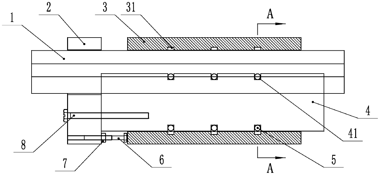
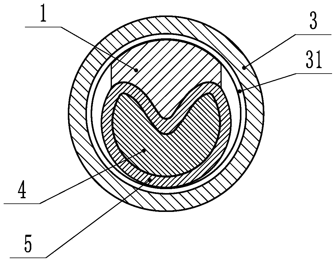
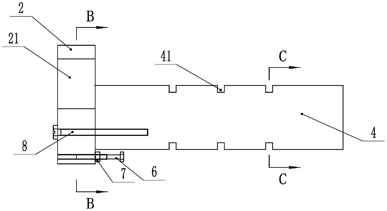
[0024] like Figure 1-8 As shown, a special tool for sealing rings embedded in hydraulic pipe straight pipes according to an embodiment of the present invention includes a main body 4 whose cross-section is crescent-shaped and the main body 4 is processed with track grooves on the crescent-shaped cross-section 41. The left side of the main body 4 is fixedly connected to a base 2 through bolts 8. The base 2 is processed with a guide hole 21 in the upper half. The movable rod 1 is matched through the guide hole 21 and extends into the upper half of the main body 4. The sealing ring 5 is embedded in the track groove 41 under the extrusion of the movable rod 1; wherein, the depth of the track groove 41 is greater than the thickness of the sealing ring 5, the lower part of the track groove 41 is a part of the arc, and the upper part is a concave part 411; the movable rod 1 The lower part is the extrusion part 11, the extrusion part 11 is matched with the recessed part 411, and the ...


PUM


Abstract

The invention discloses a special tool for embedding a sealing ring in a hydraulic pipe straight pipe. The special tool comprises a main body, the cross section of the main body is in a crescent shapeand the main body is machined with a track groove in the cross section of the crescent shape, the left side of the main body is fixedly connected with a base through a bolt, a guide hole is formed inthe upper half part of the base, a movable rod penetrates through the guide hole in a matched mode and extends into the upper half part of the main body, and the sealing ring is embedded into the track groove under the extrusion of the movable rod. Compared with manual mounting through a caliper, the special tool is efficient and labor-saving in installation, and a plurality of sealing rings canbe installed at a time; and compared with a sealing ring mounting device for a hole, the sealing ring is subjected to extrusion deformation, the sealing ring after extrusion deformation can completelyrestore deformation relative to stretching deformation, the sealing effect is good, and the special tool is more convenient and labor-saving when manual mounting is adopted.

Description

technical field [0001] The invention relates to a special tool for sealing rings embedded in straight hydraulic pipes. Background technique [0002] The use of sealing rings in hydraulic pipelines is very common. Figure 8 Shown is a common hydraulic pipe straight pipe, and now it is necessary to insert a sealing ring in the installation groove inside it. Since the outer diameter of the sealing ring is larger than the inner diameter of the hydraulic pipe straight pipe, it is very inconvenient to install manually through clamps and calipers; apply The invention patent No. 201910111683.0 discloses a hole sealing ring installation device. In the technical solution of the patent application, the movement of the pull rod 3 relative to the main body 2 causes the sealing ring sleeved on the card groove 22 to be stretched and deformed. , when the pull rod 3 is reset, the sealing ring recovers and deforms and is sleeved into the corresponding workpiece. In actual use, it is found tha...

Claims


Application Information

Patent Timeline
IPC IPC(8): B25B27/00
CPCB25B27/0028
Inventor 於金安钟从海李丹红
Owner 浙江柏润机械有限公司
Learn More