Pulling device of knitting machine

A pulling device and mechanical technology, applied in knitting, weft knitting, warp knitting, etc., can solve problems such as poor control of pulling force, achieve the effect of ensuring quality and avoiding coil elongation

Pending Publication Date: 2020-01-14
NINGBO CIXING
View PDF0 Cites 6 Cited by
  • Summary
  • Abstract
  • Description
  • Claims
  • Application Information

AI Technical Summary

Problems solved by technology

At present, the rake pull is completed by the double action of the tension spring and the self-weight of the rake, and the control of the pull force is poor.

Method used


Image

  • Pulling device of knitting machine
  • Pulling device of knitting machine
  • Pulling device of knitting machine

Examples


Embodiment Construction

[0023] The specific embodiment of the specific solution of the present invention will be further elaborated in conjunction with the accompanying drawings.

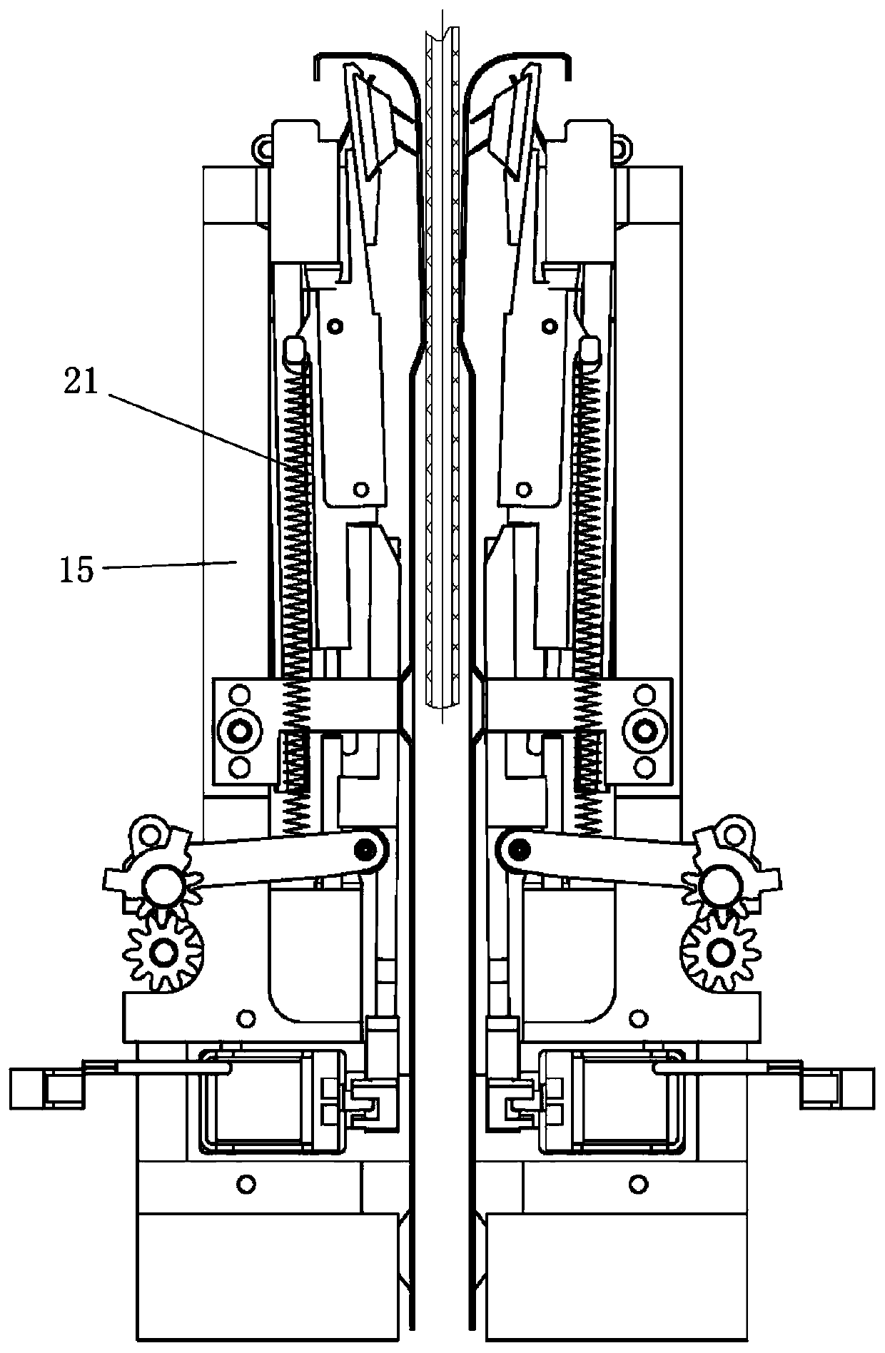
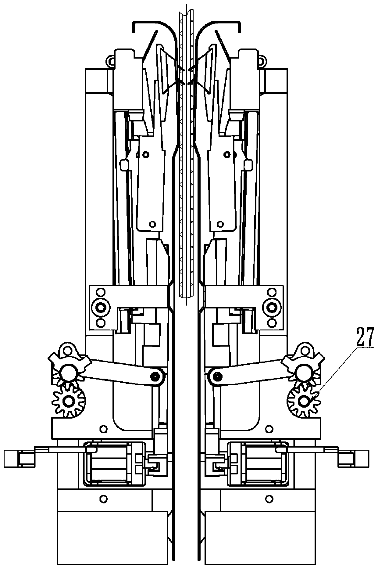
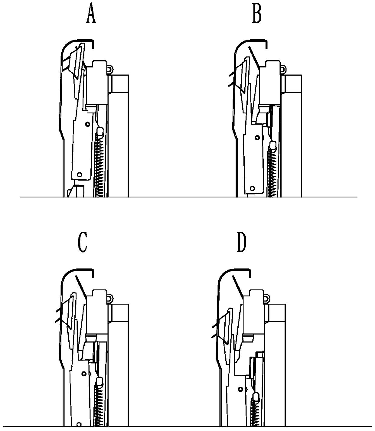
[0024] As shown in the figure, a pulling device of a knitting machine includes several rake-type pulling mechanisms, and each rake-type pulling mechanism includes a gripper seat 2, a gripper seat separation block 3, a lifting seat 5 and a fixed seat 15. Above the gripper seat 2, a gripper 4 is provided through the separation block 3 of the gripper seat. The front end of the gripper seat 2 is also provided with a guard plate 1, and the guard plate 1 is provided with a plurality of long shapes for the gripper 4 to move. The guard plate 1 is installed on the fixed seat 15 through the guard plate support, and the guard plate support includes the first guard plate support 14 and the second guard plate support 24, and the first guard plate support 14 and the second guard plate support 24 simultaneously hold the guard plate The p...


PUM


Abstract

The invention discloses a pulling device of a knitting machine. The pulling device comprises a plurality of rake type pulling mechanisms; each rake type pulling mechanism comprises a claw assembly lift base, a claw assembly fixture and a stop mechanism; a regulating mechanism is arranged on the side of the fixture; the stop mechanism is arranged below a regulating mechanism beside the fixture; theclaw assembly comprises a claw holder and a claw holder separator block, a claw is arranged on the upper portion of the claw holder through the claw holder separator block and the claw holder is mounted on the lift base; a claw roller shaft and a claw holder rotating shaft are arranged on a linear bearing block up to down, the claw holder is mounted on the claw roller shaft and the claw holder rotating shaft, and the claw roller shaft is mounted in a long slot of the linear bearing block; the claw roller shaft moves reciprocatingly in the long slot to allow the claw holder to drive the claw holder separator block and the claw to swing inwards and outwards. The rake type pulling mechanisms of the pulling device are independent mutually, and can be selected optionally to do pulling, and thus, selective pulling to the fabric can be achieved.

Description

technical field [0001] The invention relates to the field of knitting, in particular to a pulling device of a knitting machine. Background technique [0002] At present, most of the pulling devices of knitting machines use roller devices, which are easy to implement and relatively low in cost. However, the roller devices are aimed at pulling the entire fabric at the same time, and cannot achieve selective pulling of the fabric, especially There are great limitations on the fully formed machine, and the rubber layer in the roller has a certain weariness, and the fabric will be easily deformed when pulled to a certain extent, which increases the scrap rate. Therefore, it is necessary to install this rake pulling device on the roller device. The rake pulling device can make up for this defect, and it can achieve selective pulling of the fabric according to the specific weaving requirements of the fabric. What adopt at present is the rake type pulling that finishes by the dual...

Claims


Application Information

Patent Timeline
Patent Type & Authority Applications(China)
IPC IPC(8): D04B15/88D04B15/92D04B27/34
CPCD04B15/88D04B15/92D04B27/34
Inventor 孙平范徐卫东李立军胡跃勇陶伯明
Owner NINGBO CIXING
Why Eureka
Try Eureka