
Intermediate reheating steam power generation system

A power generation system and reheat steam technology, applied in steam generation, steam superheating, steam boilers, etc., can solve the problems of unit failure, high-temperature reheat steam distribution, etc., to reduce the overall layout and investment costs, and realize Safe and stable operation, simple and convenient operation

Pending Publication Date: 2020-01-14
BEIJING JINGCHENGKELIN ENVIRONMENTAL PROTECTION TECH +1
View PDF0 Cites 3 Cited by
  • Summary
  • Abstract
  • Description
  • Claims
  • Application Information

AI Technical Summary

Problems solved by technology

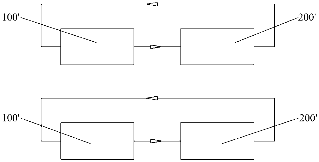
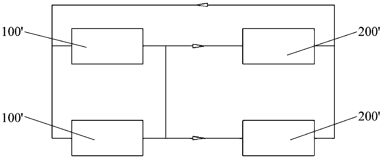
[0004] The thermal system of the two generator sets is divided into unit system (such as figure 1 shown) and parent control systems (such as figure 2 Shown) two, compared with the master control system, when a device fails to shut down in the unit system, the corresponding equipment also needs to be shut down, while the master control system is more flexible in operation, and a device failure can be removed without affecting Other equipment is running, but when the loads of the two steam turbines 200' are inconsistent, the steam turbine 200' has different pressure requirements for the two high-temperature reheat steam. allocation, causing the unit to fail to operate

Method used


Image

  • Intermediate reheating steam power generation system
  • Intermediate reheating steam power generation system
  • Intermediate reheating steam power generation system

Examples


Embodiment Construction

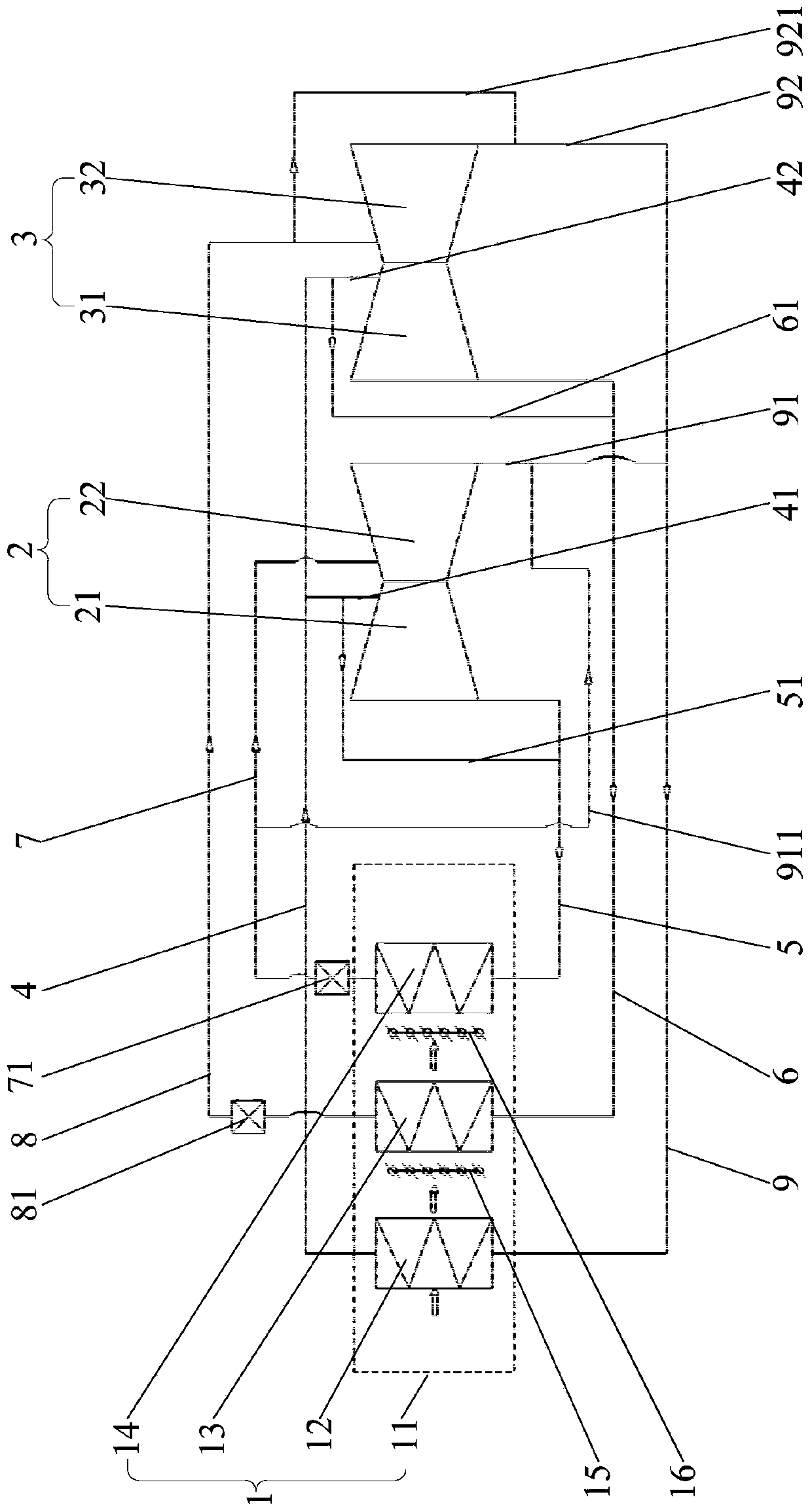
[0048] In order to have a clearer understanding of the technical solutions, objectives and effects of the present invention, the specific implementation manners of the present invention will now be described with reference to the accompanying drawings. Wherein, the use of "high pressure" and "low pressure", "high temperature" and "low temperature" is only for the convenience of relative reference between groups of terms, and does not describe any specific limitation on the modified terms. The terms "first", "second" and so on are only used for descriptive purposes, and cannot be understood as indicating or implying relative importance or implicitly specifying the number of indicated technical features. Therefore, the terms "first", " A second, etc. feature may explicitly or implicitly include one or more of these features.

[0049] Such as image 3 As shown, the present invention provides an intermediate reheat steam power generation system, which includes a boiler 1, a first s...


PUM


Abstract

The invention provides an intermediate reheating steam power generation system. The intermediate reheating steam power generation system comprises a boiler, a first steam turbine and a second turbine,the boiler comprises a superheater, a first reheater and a second reheater, the first steam turbine comprises a first high pressure cylinder and a first low pressure cylinder, the steam inlet of thefirst high pressure cylinder communicates with the outlet of the superheater, the steam exhausting opening of the first high pressure cylinder communicates with the steam inlet of the second reheater,the steam inlet of the first lower pressure cylinder communicates with the steam exhausting opening of the second reheater, and the steam exhausting opening of the first low pressure cylinder communicates with the inlet of the superheater; and the second steam turbine comprises a second high pressure cylinder and a second low pressure cylinder, the steam inlet of the second high pressure cylindercommunicates with the outlet of the superheater, the steam exhausting opening of the second high pressure cylinder communicates with the steam inlet of the first reheater, the steam inlet of the second low pressure cylinder communicates with the steam exhausting opening of the first reheater, and the steam exhausting opening of the second low pressure cylinder communicates with the inlet of the superheater. The intermediate reheating steam power generation system can reasonably distribute high-temperature and reheated steam and reduces the total system occupation area.

Description

technical field [0001] The invention relates to the technical field of steam power generation, in particular to an intermediate reheat steam power generation system. Background technique [0002] Blast furnace gas, as a by-product of the ironmaking process in iron and steel enterprises, is a high-quality secondary energy source. The blast furnace gas power generation project belongs to the energy-saving technology of the iron and steel industry that the state encourages and promotes. At present, most iron and steel enterprises are equipped with gas generator sets with medium temperature, medium pressure and above parameters. With the saturation of the development of the power industry, steam turbine factories have begun to develop in the direction of high-parameter miniaturized steam turbines, and gas power generation projects with ultra-high pressure parameters and above have emerged as the times require. . In view of the fact that the efficiency of ultra-high pressure (p...

Claims


Application Information

Patent Timeline
IPC IPC(8): F22B31/08F22G5/12F22D11/06F01K11/02F01K13/00
CPCF01K11/02F01K13/00F22B31/08F22D11/06F22G5/123Y02P80/15
Inventor 张晓凯蔡发明
Owner BEIJING JINGCHENGKELIN ENVIRONMENTAL PROTECTION TECH
Learn More