Molding device

A sub-mold and heat transfer technology, applied in the field of forming devices, can solve the problems of reduced production efficiency, increased sub-mold replacement time ratio, etc., and achieves the effect of increasing temperature regulation

Active Publication Date: 2020-01-14
KONICA MINOLTA INC
View PDF7 Cites 0 Cited by
  • Summary
  • Abstract
  • Description
  • Claims
  • Application Information

AI Technical Summary

Problems solved by technology

However, when piping for temperature adjustment is provided in the sub-mold constituting the cavity, it is necessary to disassemble and reassemble the piping every time the sub-mold is attached to and detached from the master mold, especially when molding small batches of molded parts. , the proportion of the replacement time of the sub-mold becomes higher, and there is a problem of lower production efficiency.

Method used


Image

  • Molding device
  • Molding device
  • Molding device

Examples


Embodiment Construction

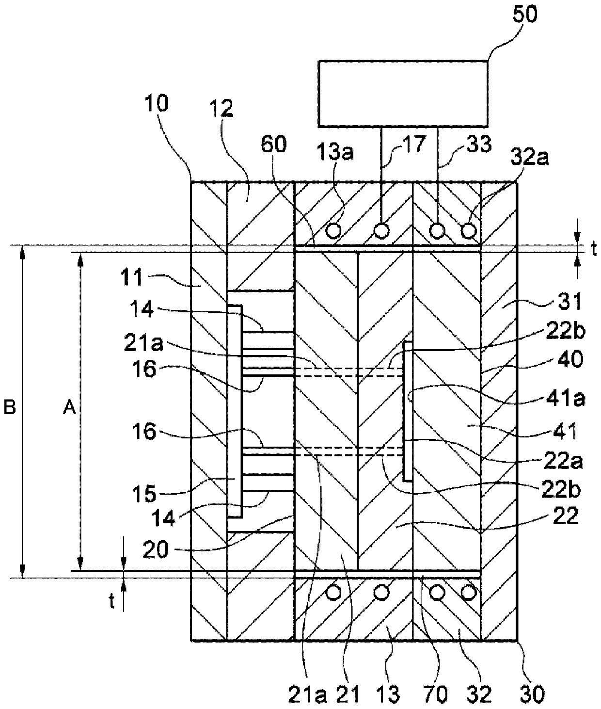
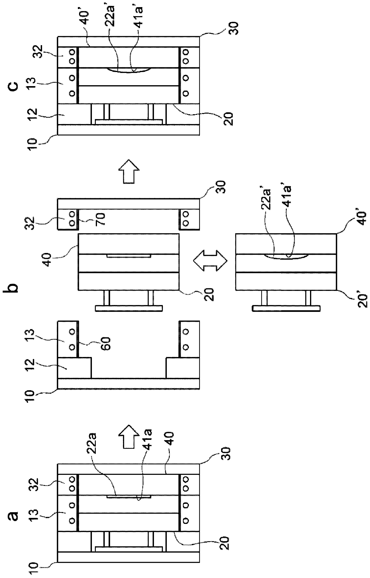
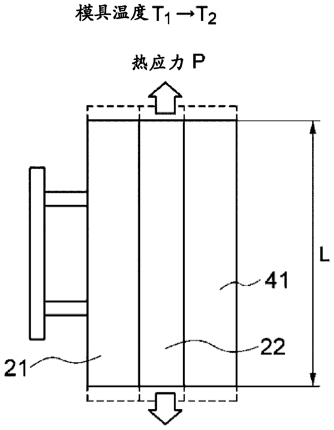
[0030] Hereinafter, embodiments of the present invention will be described with reference to the drawings. Figure 1A It is a schematic sectional view of the molding apparatus of this embodiment. The molding device has a fixed-side master mold 10 , a fixed-side sub-die 20 , a movable-side master mold 30 , a movable-side sub-die 40 , a temperature adjustment unit 50 , a fixed-side elastic member 60 , and a movable-side elastic member 70 . The master mold is composed of the fixed-side master mold 10 and the movable-side master mold 30, and the sub-mould is composed of the fixed-side sub-mould 20 and the movable-side sub-mould 40. The fixed-side elastic member 60 and the movable-side elastic member 70 are capable of elastic deformation. heat transfer components.

[0031] The fixed-side master mold 10 made of steel has a fixed-side receiving plate 11 , a first frame body 12 mounted on the fixed-side receiving plate 11 , and a second frame body 13 mounted on the first frame body 12...


PUM

PropertyMeasurementUnit
thicknessaaaaaaaaaa
elastic modulusaaaaaaaaaa
thermal conductivityaaaaaaaaaa

Abstract

A molding device comprises an insert mold and a matrix to which the insert mold is replaceably attached. The matrix includes a pipe through which a temperature adjustment fluid flows. Between the insert mold and the matrix, an elastically deformable heat transmission member that contacts both the insert mold and the matrix during at least molding is arranged. Thus, a molding device that is capableof effectively adjusting, while using a matrix to which an insert mold is replaceably attached, a temperature of the insert mold without increasing a mold manufacturing cost or time and effort for replacement can be provided.

Description

technical field [0001] The present invention relates to a molding device incorporating a pipe for temperature adjustment. Background technique [0002] In a general injection molding apparatus, molten resin is injected into a cavity of a mold, and after the resin is solidified, the mold is released to take out a molded product. However, as a recent trend, multi-variety and small-lot molded parts are increasing. In order to mold a variety of resin products, it is necessary to make molds for each product with a different shape. However, when making molds for each product, the cost of small-lot products increases, and mold production also takes time. Therefore, a box-type technique has been developed in which a master mold has a common part of the mold and a sub-mold having a product-specific part (cavity shape) can be replaced. Through the box-type technology, the cost and time of mold making for each product can be suppressed, especially for small batch products, because th...

Claims


Application Information

Patent Timeline
Patent Type & Authority Applications(China)
IPC IPC(8): B29C45/26B29C33/04
CPCB29C33/04B29C45/2673B29C45/7331B29K2905/00
Inventor 水金贵裕
Owner KONICA MINOLTA INC
Why Eureka
Try Eureka