A Furnace Pressure Control System

A pressure control and furnace technology, applied in the direction of electric controllers, controllers with specific characteristics, etc., can solve the problems of large damage to the gate valve, low surface temperature, unfavorable furnace pressure control, etc., and achieve the effect of saving energy

Active Publication Date: 2022-03-01
ANHUI FENGHUI METAL
View PDF12 Cites 0 Cited by
  • Summary
  • Abstract
  • Description
  • Claims
  • Application Information

AI Technical Summary

Problems solved by technology

[0004] Due to its fully open or fully closed structural design, when the gate valve encounters extremely fast output heat, the surface temperature will be too low, and thermal bridges will easily occur, which will cause condensation or expansion of the gate valve output itself, which will damage the gate valve itself. Large, and not conducive to pressure control in the furnace

Method used


Image

  • A Furnace Pressure Control System
  • A Furnace Pressure Control System
  • A Furnace Pressure Control System

Examples


Embodiment Construction

[0020] In order to make the technical means, creative features, goals and effects achieved by the present invention easy to understand, the present invention will be further elaborated below in conjunction with specific embodiments, but the following embodiments are only preferred embodiments of the present invention, not all. Based on the examples in the implementation manners, other examples obtained by those skilled in the art without making creative efforts all belong to the protection scope of the present invention. The experimental methods in the following examples, unless otherwise specified, are conventional methods, and the materials, reagents, etc. used in the following examples, unless otherwise specified, can be obtained from commercial sources.

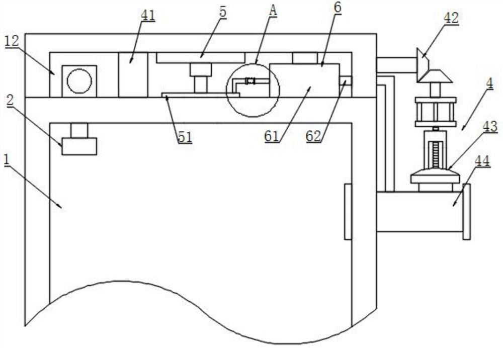
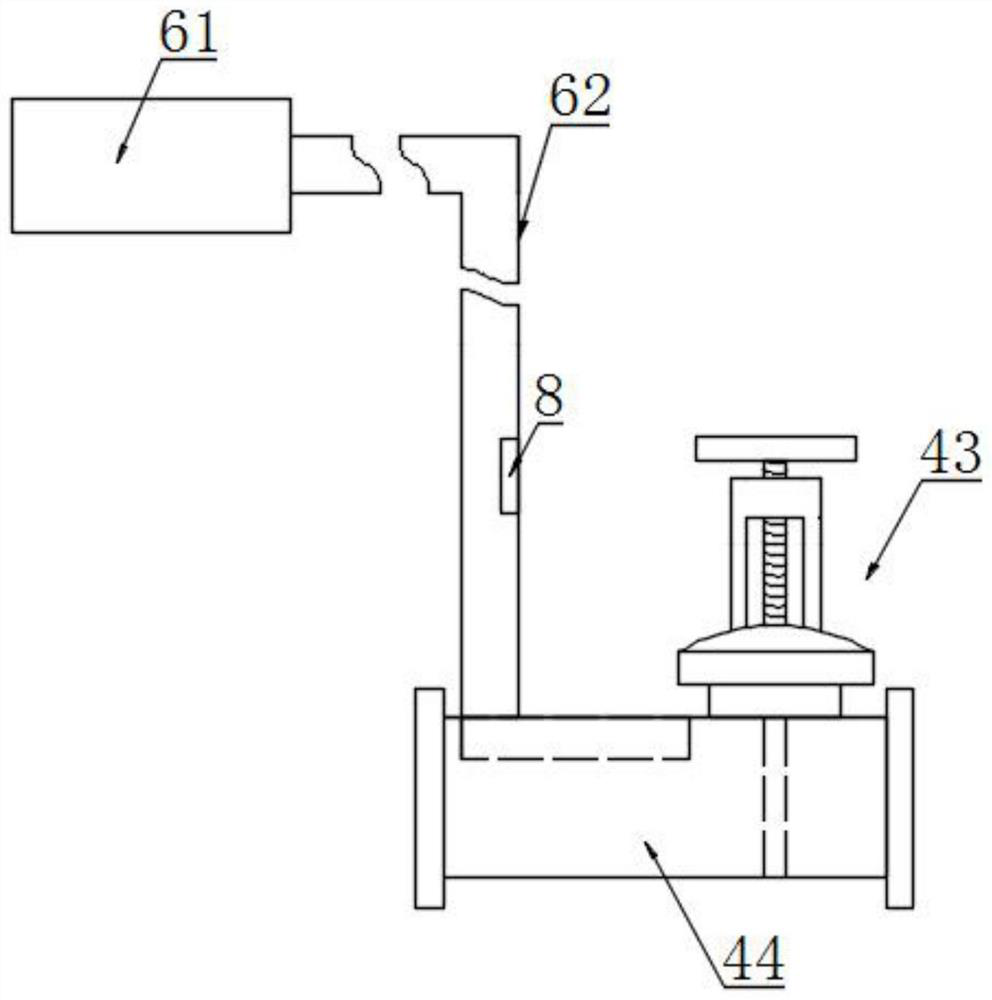
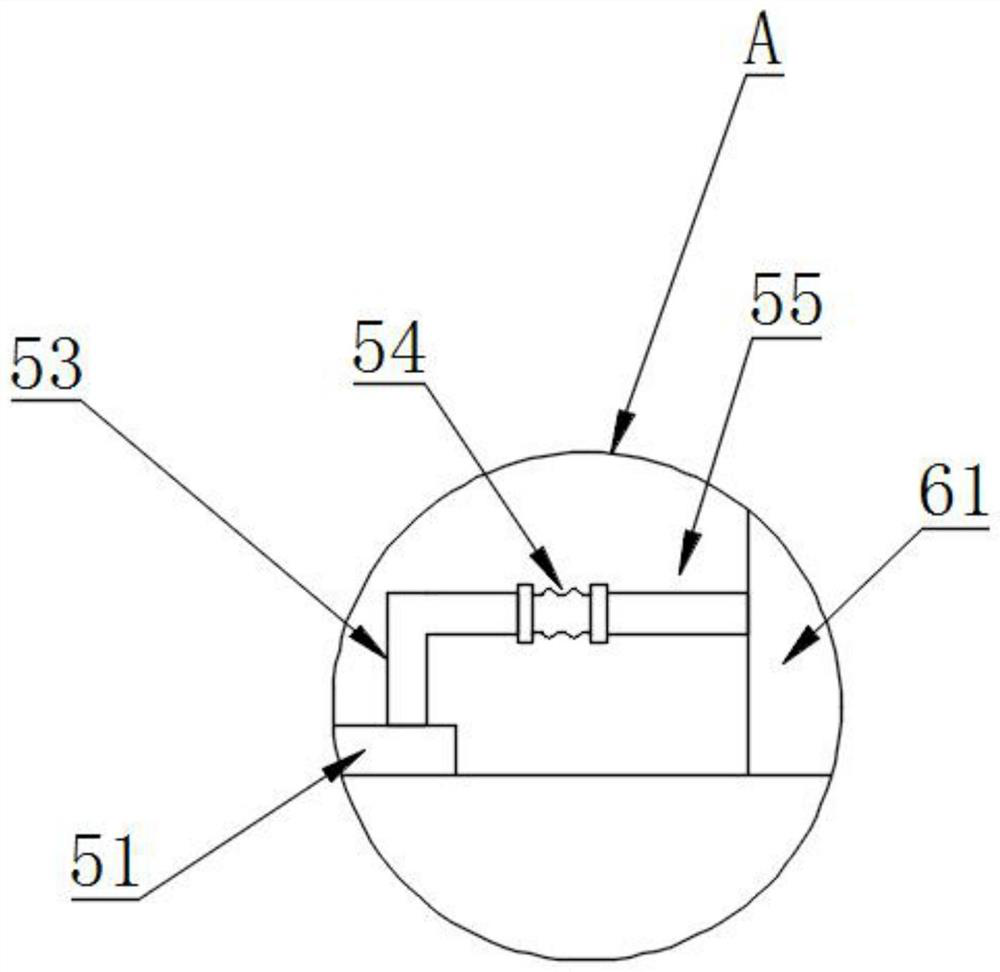
[0021] Please refer to Figure 1-6 As shown, the present invention provides a furnace pressure control system, including a furnace body 1, a control element cavity 12 is provided on the outer top surface of the furnace bo...


PUM


Abstract

The invention discloses a furnace pressure control system, which comprises a furnace body, a control element cavity is arranged on the outer top surface of the furnace body, and a pressure detection module, an air heating module, an air input module and a PID module are arranged inside the control element cavity; The air heating module includes an electric control turntable, and the bearing of the electric control turntable penetrates the top wall of the furnace body, and keeps the bottom surface flat; There are heat conduction holes, and the heat conduction holes and the heat conduction strips are rotated and adapted; the side wall of the furnace body is also pierced with a pressure discharge pipe, and a gate valve is installed on the pressure discharge pipe; the air input module includes a heat-insulated and pressure-resistant pipe. The output port is located on the side of the output part of the gate valve; the invention prevents the output part of the gate valve from thermal bridge phenomenon when encountering extreme heat, thereby effectively protecting the gate valve; effectively controlling the temperature adjustment on the output part of the gate valve without connecting external heat, saving energy.

Description

technical field [0001] The invention relates to a pressure control system, in particular to a furnace pressure control system. Background technique [0002] In the pressure control process of the furnace, a differential pressure transmitter is generally installed on the top of the furnace to monitor the pressure in the furnace in real time, and the opening of the gate valve is controlled by the PID of the PLC to realize the micro positive pressure in the furnace. [0003] The gate valve is a gate of the opening and closing part. The direction of movement of the gate is perpendicular to the direction of the fluid. The gate valve can only be fully opened and fully closed, and cannot be adjusted or throttled. The gate valve is sealed by the contact between the valve seat and the gate plate. Usually, the sealing surface will be surfacing with metal materials to increase wear resistance, such as surfacing welding 1Cr13, STL6, stainless steel, etc. There are rigid gate valves and...

Claims


Application Information

Patent Timeline
Patent Type & Authority Patents(China)
IPC IPC(8): G05B11/42
CPCG05B11/42
Inventor 张育玮张枫杨勇
Owner ANHUI FENGHUI METAL
Why Eureka
Try Eureka