
Pump valve block machining and cleaning treatment system

A technology for cleaning treatment and valve block, which is applied in the direction of using tools for cleaning, cleaning methods and utensils, chemical instruments and methods, etc. The degree of cleaning, increase the scraping force, and improve the effect of the cleaning effect

Active Publication Date: 2020-01-17
广州白云液压机械厂有限公司
View PDF6 Cites 2 Cited by
  • Summary
  • Abstract
  • Description
  • Claims
  • Application Information

AI Technical Summary

Problems solved by technology

[0003] 1. There are multiple through holes on the common valve block, but usually when the outer surface of the valve block is directly treated, the cleaning of the through holes is ignored, or the through holes are not cleaned properly, and the surface cleaning process During the process, some impurities will fall into the through hole and form accumulations, causing the impurities in the through hole to increase instead of decrease, but the purpose of cleaning the valve block cannot be achieved;
[0004] 2. Because the valve block is a polyhedron structure, it will increase the working time if the surface is cleaned one by one. On the premise that the through holes need to be cleaned, the working efficiency of the whole process is low, and the valve block needs to be cleaned one by one. Flip, in this process, it will increase the probability of impurities falling into the through hole or sticking impurities on the cleaned surface, and the cleaning effect is poor

Method used


Image

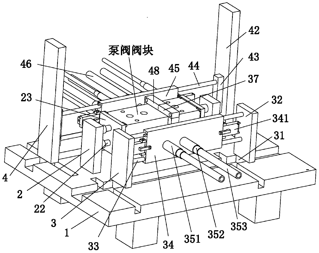
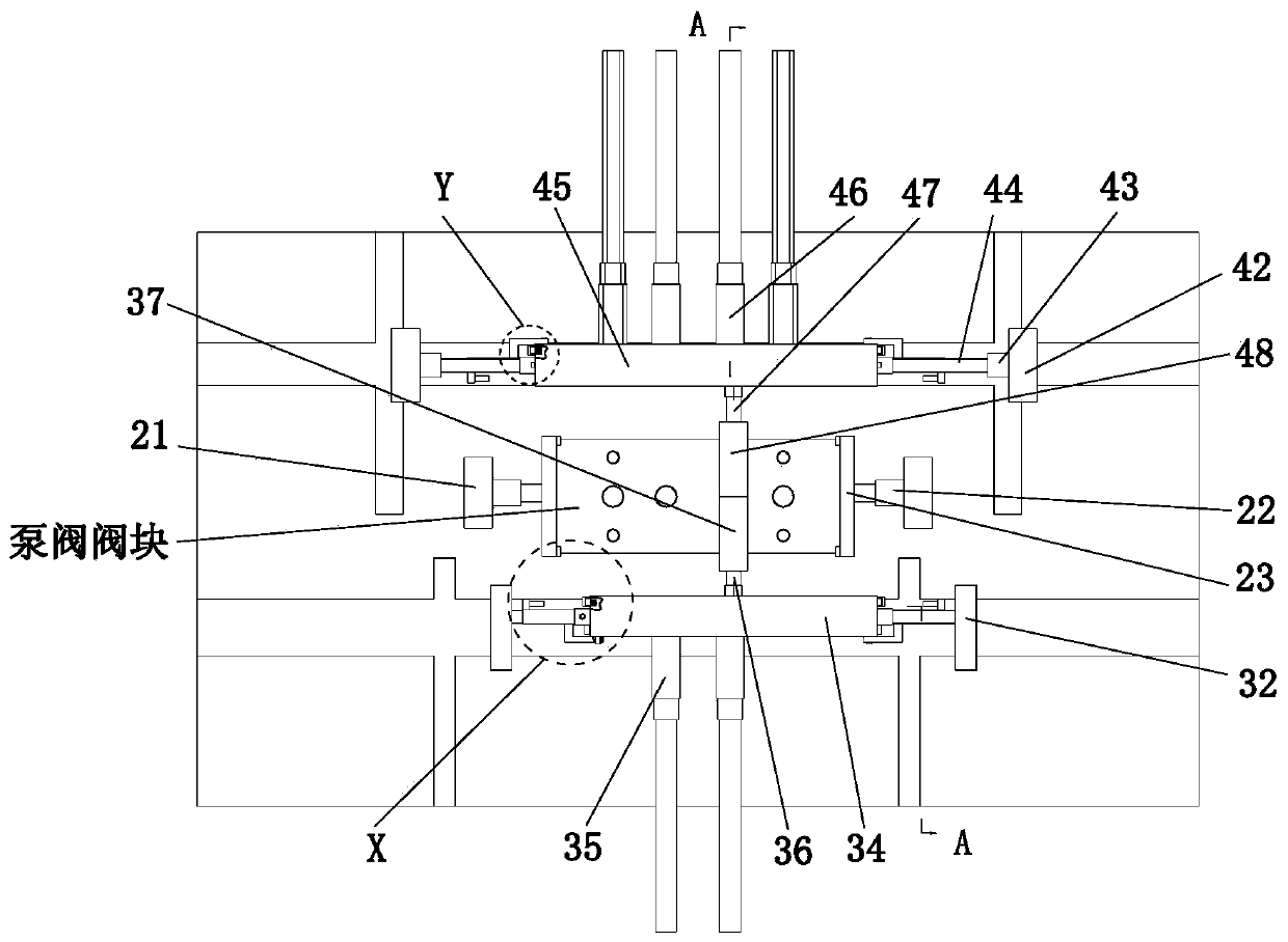
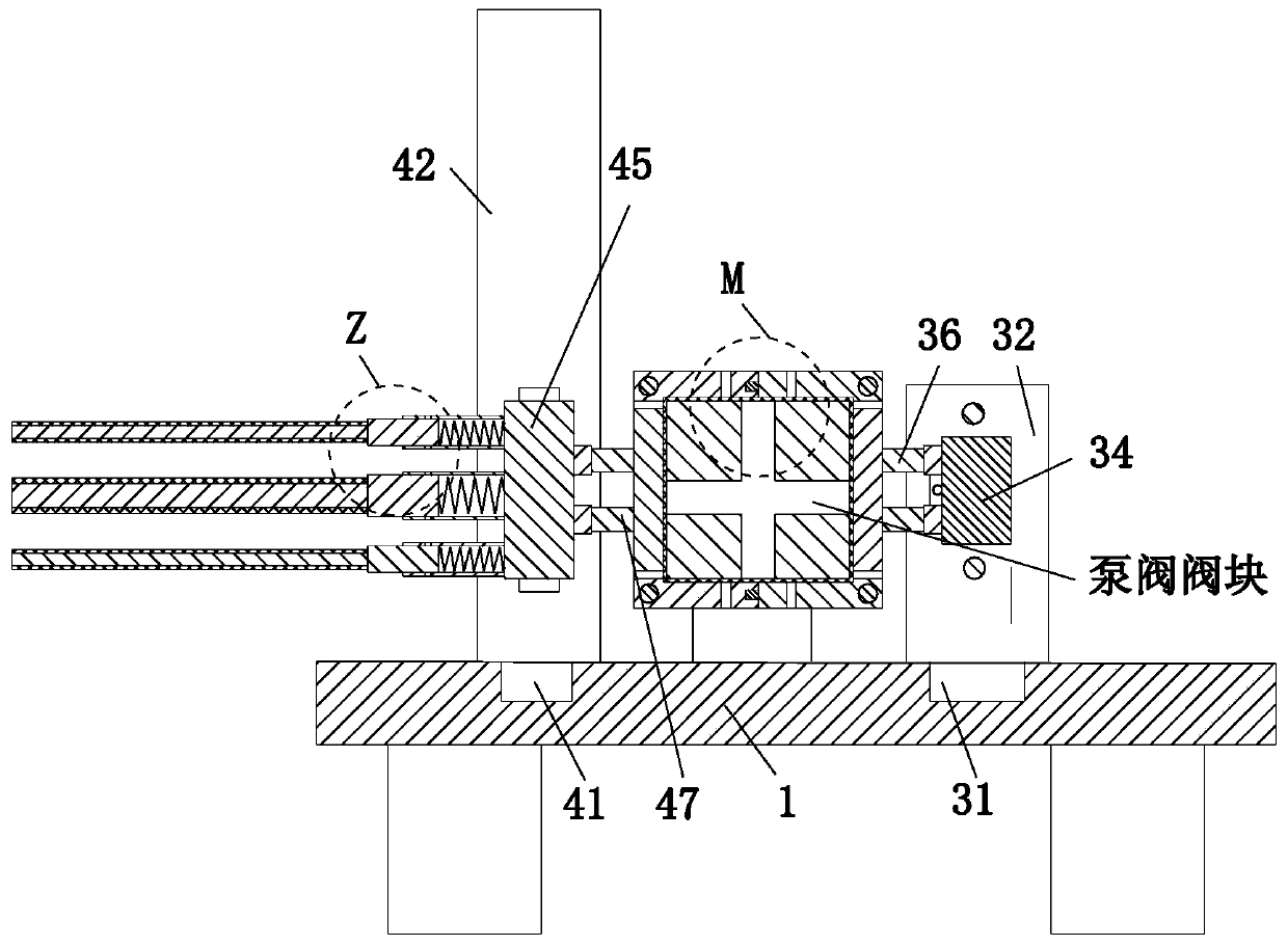
  • Pump valve block machining and cleaning treatment system
  • Pump valve block machining and cleaning treatment system
  • Pump valve block machining and cleaning treatment system

Examples


Embodiment Construction

[0029] The embodiments of the present invention will be described in detail below with reference to the accompanying drawings, but the present invention can be implemented in many different ways as defined and covered by the claims.

[0030] Such as Figure 1 to Figure 7 As shown, a pump valve valve block processing and cleaning system includes a workbench 1, a clamping device 2, a cleaning device 3 and a scraping device 4, and the clamping device 2 is installed in the middle of the upper end surface of the workbench 1, The front end of the upper end surface of the workbench 1 is installed with a cleaning device 3 through a sliding fit, and the rear end of the upper end surface of the workbench 1 is installed with a scraping device 4 through a sliding fit. The clamping device 2 is located between the cleaning device 3 and the scraping device 4. between.

[0031] The clamping device 2 includes a fixed plate 21, an electric push rod 22, a splint 23 and an inverted L-shaped bump...


PUM


Abstract

The invention relates to a pump valve block machining and cleaning treatment system. The pump valve block machining and cleaning treatment system comprises a workbench, a clamping device, a cleaning device and a scraping and washing device, wherein the clamping device is mounted in the middle of the upper end face of the workbench; the cleaning device is mounted at the front end of the upper end face of the workbench in a sliding fit manner; the scraping and washing device is mounted at the rear end of the upper end face of the workbench in a sliding fit manner; and the clamping device is located between the cleaning device and the scraping and washing device. According to the pump valve block machining and cleaning treatment system, a continuous and comprehensive design concept is adoptedfor cleaning a pump valve block, the valve block is comprehensively cleaned, and the cleaning degree is improved; and the scraping and washing device is adopted for cleaning the surface of the valveblock and through holes, surface cleaning is conducted before the through holes are cleaned, and the phenomenon that part of impurities fall into the through holes and are accumulated is avoided.

Description

technical field [0001] The invention relates to the field of valve block cleaning machinery, in particular to a processing and cleaning system for valve blocks of pump valves. Background technique [0002] The valve block is used in the electro-hydraulic servo control system. In the TRT device, it belongs to one of the eight subsystems. The accuracy error of the electro-hydraulic servo control system directly affects the control of each stage of the TRT system. It plays an important role. The pump valve is A general term for pumps and valves. A pump is an energy conversion machine that transfers the mechanical energy of the power machine or the energy of other energy sources to the liquid being transported, so that the energy of the liquid is increased for a certain operation, and it is also used for air. For example, vacuum pumps, etc., pumps can be divided into water pumps, oil pumps, sewage pumps, centrifugal pumps, mud pumps and other types. After the valve block is proc...

Claims


Application Information

Patent Timeline
IPC IPC(8): B08B1/00B08B13/00
CPCB08B13/00B08B1/30
Inventor 方坤棉朱乐乐
Owner 广州白云液压机械厂有限公司
Learn More