Asphalt stirring and manufacturing device

A technology for manufacturing equipment and asphalt mixing, which is applied in the field of asphalt mixing manufacturing equipment, can solve the problems of reducing equipment working efficiency, single structure, production stagnation, etc., achieve the effect of easy tearing and mixing, and improve the effect

Inactive Publication Date: 2020-01-17
齐嘉蕾
View PDF0 Cites 2 Cited by
  • Summary
  • Abstract
  • Description
  • Claims
  • Application Information

AI Technical Summary

Problems solved by technology

[0002] Generally, asphalt needs to be mixed and heated before it can be applied to actual industrial production. There are many problems in this process, such as: due to the high viscosity of asphalt, it is not easy to make the asphalt continuous materials mutually Separate and mix sand and gravel into the asphalt, there will be some continuous asphalt attached to the inside of the equipment in the long-term use of the equipment, so that the equipment is prone to downtime during subsequent work or continuous processing. On the one hand, personnel are required to carry out rapid repairs. On the one hand, it increases the labor burden of personnel. On the other hand, the production stagnation caused by equipment shutdown is also the reason that hinders the work efficiency of equipment. For the laying of asphalt, the structure adopted is relatively simple. Because the mechanical conveying method will be bonded to the conveyor, the asphalt conveying efficiency will be reduced, which will also reduce the working efficiency of the equipment.

Method used


Image

  • Asphalt stirring and manufacturing device
  • Asphalt stirring and manufacturing device
  • Asphalt stirring and manufacturing device

Examples


Embodiment Construction

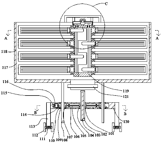
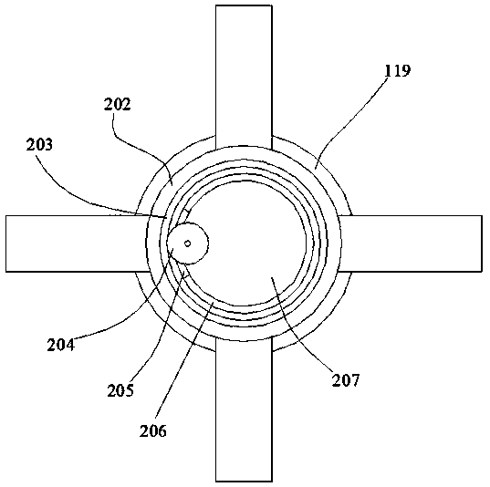
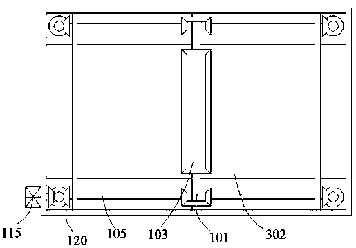
[0020] Such as Figure 1-Figure 4 As shown, the present invention is described in detail. For the convenience of description, the orientations mentioned below are now stipulated as follows: figure 1 The up, down, left, right, front and back directions of the projection relationship itself are consistent. A kind of asphalt mixing manufacturing equipment of the present invention includes a top box body 118, and an open top storage chamber 117 is arranged in the top box body 118. The top storage chamber 117 An on-off valve 121 is communicated in the lower end wall, and a symmetrical support frame 407 is fixed on the upper end surface of the top box body 118, and symmetrical top fixing columns 402 are fixed between the supporting frames 407, and the top fixing columns 402 is fixed with a cylinder 206 on the lower end surface, and the cylinder 206 is provided with a stirring device for stirring the asphalt in the top chamber 117 at high temperature, and the lower end surface of the...


PUM


Abstract

The invention discloses an asphalt stirring and manufacturing device. The asphalt stirring and manufacturing device comprises a top box body, a top accommodating cavity with an opening is formed in the top box body, and a switch valve is arranged on the lower end wall of the top accommodating cavity in a communicating manner. Supporting frames which are symmetrical front and back are fixedly arranged on the upper end face of the top box body, symmetrical top fixing columns are fixedly arranged between the supporting frames, and cylinders are fixedly arranged on the lower end faces of the top fixing columns. A stirring device for stirring asphalt in the top accommodating cavity at a high temperature is arranged in each cylinder, a plurality of lifting external threaded rods are fixedly arranged on the lower end surface of the top box body, and the outer sides of the lifting external threaded rods is provided with the rotary releasing devices which are matched with the lifting external threaded rods and are used for placing the asphalt and releasing the asphalt to the ground in a rotary releasing manner, thereby preventing from being adhered by the asphalt during the stirring process. The rotation directions between the middle mounting box bodies of different levels are reverse, so that the asphalt is easier to tear and stir, and the stirring effect is improved.

Description

technical field [0001] The invention relates to the technical field of asphalt production, in particular to asphalt mixing manufacturing equipment. Background technique [0002] Asphalt generally needs to be mixed and heated before it can be applied to actual industrial production. There are many problems in this process, such as: due to the high viscosity of asphalt, it is not easy to make the asphalt continuous materials mutually Separate and mix sand and gravel into the asphalt, there will be some continuous asphalt attached to the inside of the equipment in the long-term use of the equipment, so that the equipment is prone to downtime during subsequent work or continuous processing. On the one hand, personnel are required to carry out rapid repairs. On the one hand, the labor burden of personnel is increased. On the other hand, the production stagnation caused by equipment shutdown is also the reason that hinders the efficiency of equipment. For the laying of asphalt, th...

Claims


Application Information

Patent Timeline
IPC IPC(8): E01C19/10
CPCE01C19/10E01C19/1013
Inventor 齐嘉蕾
Owner 齐嘉蕾
Why Eureka
Try Eureka