Automatic climbing truss and its top leveling device
A technology for leveling devices and trusses, which is applied to the accessories of scaffolding, scaffolding supported by house structures, buildings, etc. It can solve problems such as unbalanced and unstable tops, and achieve the goals of facilitating construction, improving work efficiency, and improving safety performance. Effect
- Summary
- Abstract
- Description
- Claims
- Application Information
AI Technical Summary
Problems solved by technology
Method used
Image

Examples
Embodiment 2
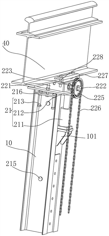
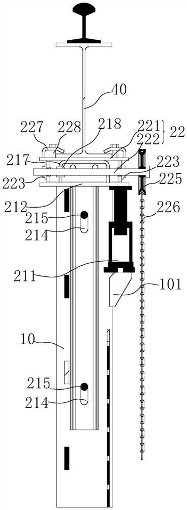
[0051] like figure 2 and image 3 As shown, the second adjusting member 222 of the present application is provided with a sprocket 225 , and a chain 226 is wound around the sprocket 225 , and the chain 226 is used to drive the sprocket 225 to rotate so as to drive the cover plate 221 to move in the horizontal direction. Among them, with image 3 The view direction is used as a reference direction, the sprocket 225 is arranged on the right of the second adjustment part 222, and the leveling device 20 at the top of the truss can drive the sprocket 225 to rotate by pulling the chain 226, so that the second adjustment part 222 drives the cover plate 221 in the installation The connecting seat 212 moves in the horizontal direction to adjust the space size of the automatic climbing truss in the horizontal direction.
[0052] It should be noted that the sprocket 225 and the chain 226 can be composed of a chain hoist structure, and the fixed connection technology between the chain ...
Embodiment 3
[0054] like figure 2 and image 3 As shown, the top surface of the cover plate 221 of the present application also protrudes from the locking fixing plate 227 for fixing the rail bearing beam 40, and the locking fixing plate 227 is provided with a third fastener 228, and the third fastener 228 Insert the cover plate 221 through the locking and fixing plate 227 to fix the rail bearing beam 40 on the cover plate 221 . Among them, with image 3 The viewing direction is used as a reference direction. Locking and fixing plates 227 are provided on both sides of the cover plate 221 . The locking and fixing plates 227 fasten the rail support beam 40 to the top surface of the cover plate 221 by pressing. The locking and fixing plate 227 is mainly used for fixed connection with the rail bearing beam 40 .
[0055] It should be noted that two third fasteners 228 are arranged on the locking and fixing plate 227 , and the third fasteners 228 may be bolts, screws, pins and the like.
Embodiment 4
[0057] like Figure 4 to Figure 7 As shown, the climbing device 30 of the present application includes a climbing seat 31 , a driving source 32 , a hook plate 33 , a load-bearing shift gear 34 and an elastic element 35 . The climbing seat 31 is movably clamped on the truss guide rail 10, and the two sides of the climbing seat 31 are provided with clamping plates 311. The clamping plates 311 on both sides form an accommodation space that matches the truss guide rail 10, and are located on both sides of the accommodation space. A clamping column 312 protrudes from the clamping plate 311; the truss guide rail 10 is arranged in the accommodation space and is clamped on the truss guide rail 10 through the clamping column 312 so that the climbing seat 31 moves on the truss guide rail 10. The base of the driving source 32 is connected with the climbing seat 31, the output shaft of the driving source 32 is connected with the truss guide rail 10, and the driving source 32 can drive the...
PUM
 Abstract
Description
Claims
Application Information
 - R&D
- Intellectual Property
- Life Sciences
- Materials
- Tech Scout
- Unparalleled Data Quality
- Higher Quality Content
- 60% Fewer Hallucinations
Browse by: Latest US Patents, China's latest patents, Technical Efficacy Thesaurus, Application Domain, Technology Topic, Popular Technical Reports.
© 2025 PatSnap. All rights reserved.Legal|Privacy policy|Modern Slavery Act Transparency Statement|Sitemap|About US| Contact US: help@patsnap.com