A carburetor structure for preventing oil cut-off in bumpy road sections

A carburetor and oil-cutting technology, applied in carburetors, machines/engines, engine components, etc., can solve problems such as engine flameout, float swinging, affecting the timeliness of fuel supply, etc., to ensure normal state and avoid flameout Effect

Active Publication Date: 2020-06-26
芜湖太阳神汽摩配制造有限公司
View PDF6 Cites 0 Cited by
  • Summary
  • Abstract
  • Description
  • Claims
  • Application Information

AI Technical Summary

Problems solved by technology

[0003] Most of the existing carburetors use floats to control the oil intake. In daily use, when vehicles such as automobiles or motorcycles pass through bumpy roads, the vibration in the carburetor will be too severe due to excessive vibration. The float of the car is swaying, although the range is not large, but it will affect the timeliness of fuel supply, and if the oil circuit is cut off, the engine will stall due to insufficient fuel supply, which will cause the car owner to get into trouble

Method used


Image

  • A carburetor structure for preventing oil cut-off in bumpy road sections
  • A carburetor structure for preventing oil cut-off in bumpy road sections
  • A carburetor structure for preventing oil cut-off in bumpy road sections

Examples


Embodiment 1

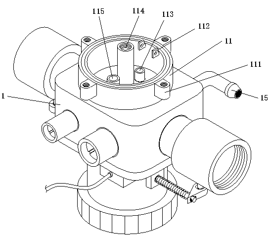
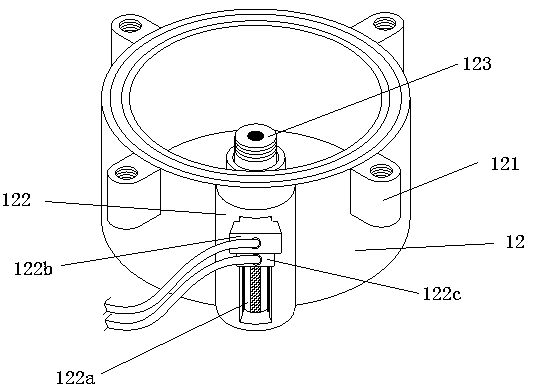
[0032] Embodiment one, please emphatically refer to the attached Figure 1-6As shown in the figure, a carburetor structure for preventing oil cut-off in a bumpy road section includes a carburetor body 1, an oil shell fixing seat 11 is arranged on one side of the carburetor body 1, and the oil shell fixing seat 11 is anastomosedly connected with an oil shell 12, a magnetic induction device 122 is vertically provided on one side of the outer wall of the oil shell 12, and a guide rail groove 122a is vertically opened on the housing of the magnetic induction device 122. An electromagnetic inductor 122b and an electromagnet locator 122c are provided, the top of the electromagnet locator 122c is connected to the bottom housing of the electromagnetic inductor 122b, and the electromagnetic inductor 122b and the electromagnet locator 122c are all in sliding connection with the guide rail groove 122a; one end of the electromagnetic inductor 122b close to the oil shell 12 is provided wit...

Embodiment 2

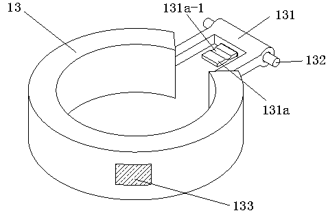
[0033] Embodiment two, please emphatically refer to the attached figure 1 , 3 As shown in and 4, the buoy 13 includes a connecting bridge 131, the two bridge seats of the connecting bridge 131 are thermally fused connected with the opening of the buoy 13, and the inside of the bridge body of the connecting bridge 131 is horizontally The central axis is penetrated with a limit pin 132, and the two ends of the limit pin 132 extend to both sides of the connecting bridge 131 and are symmetrically inserted and connected with a single-hole fixing piece 112. The two single-hole fixing pieces 112 and the two The inner wall of one side of the oil shell fixing seat 11 is connected; the outer wall of one end of the connecting bridge 131 close to the opening of the float 13 is thermally connected with a tongue piece 131a, and the upper and lower sides of the tongue piece 131a are symmetrically arranged. There is an arc-shaped groove 131a-1, and the tongue 131a is covered with a triangula...

Embodiment 3

[0034] Embodiment three, please emphatically refer to the attached figure 1 , 2 As shown in and 4, four first single-hole fixing ears 111 are equally divided on the outer wall of the oil shell fixing seat 11, and the inner center of the oil shell fixing seat 11 is provided with a main volume channel column tube 114, so One end of the main volume channel column tube 114 close to the two single-hole fixing pieces 112 is provided with an oil inlet inner column tube 113, and the end of the main volume channel column tube 114 far away from the oil inlet inner column tube 113 is provided with an auxiliary Measuring hole column tube 115; four second single-hole fixed ears 121 are equally divided on the outer wall of the end of the oil shell 12 near the opening, and the plurality of second single-hole fixed ears 121 are connected with the plurality of first single-hole fixed ears. The hole fixing ears 111 are connected one by one, and the connection method is fixed by bolts; the cent...


PUM


Abstract

The invention discloses a carburetor structure capable of preventing fuel cut-off in a bumpy section. The carburetor structure mainly comprises an oil crust base, an oil crust, a magnetic induction device and a floater; magnet sheets are symmetrically arranged on the floater, the positions of the magnet sheets on the floater are tracked by using an electromagnetic induction component module through the magnetic induction device arranged on the outer wall of the oil crust, the magnetic induction device slides up and down in a guide rail groove to be matched with the movement of the floater to induce the swing condition of the floater in a real-time manner, then digitized control is performed by an electromagnetic induction processing chip, when the swing frequency of the floater is too high, the electromagnetic induction processing chip sends a command to a chip executor, and power is supplied to an electromagnet at the front end to generate a magnetic attraction force to form magneticattraction with the magnet sheets on the floater to achieve the purpose of control the floater. Through the control to floater fluctuation, oil inlet of a carburetor is not continuously cut off due todrastic fluctuation, and the phenomenon that an engine is flamed out in the bumpy section is avoided.

Description

technical field [0001] The invention mainly relates to the technical field of carburetors, in particular to a carburetor structure for preventing oil cut-off in bumpy road sections. Background technique [0002] A carburetor is a mechanical device that mixes a certain proportion of gasoline with air under the vacuum generated by the engine. As a precise mechanical device, the carburetor uses the kinetic energy of the inhaled air flow to realize the atomization of gasoline. Its important role in the engine can be called the "heart" of the engine. Its complete device should include starting device, idle speed device, medium load device, full load device and acceleration device. The carburetor will automatically mix the corresponding concentration according to the requirements of different working conditions of the engine, and output the corresponding amount of mixed gas. In order to make the mixed gas mixed evenly, the carburetor also has the function of atomizing the fuel. ...

Claims


Application Information

Patent Timeline
Patent Type & Authority Patents(China)
IPC IPC(8): F02M5/02F02M5/12F02M5/16
CPCF02M5/02F02M5/12F02M5/16
Inventor 徐荣义彭润富
Owner 芜湖太阳神汽摩配制造有限公司
Why Eureka
Try Eureka