
Axis torque sensor

A sensor and axial torque technology, applied in the field of sensors, can solve the problems of insufficient connection between the sensor and the stepping rod, no protective structure for the sensor, and inconvenient connection of the sensor, etc., so as to improve safety, improve the use effect and prolong the service life.

Inactive Publication Date: 2020-01-17
苏州至上软件科技有限公司
View PDF0 Cites 0 Cited by
  • Summary
  • Abstract
  • Description
  • Claims
  • Application Information

AI Technical Summary

Problems solved by technology

[0003] The existing axial torque sensor has certain defects in use. The connector of the sensor is inconvenient to connect with the pedal lever on the electric bicycle, and the connection between the sensor and the pedal lever is not firm enough. The sensor has no protective structure during use, and the sensor is vulnerable to damage. The damage caused by the collision of foreign objects has brought a certain impact on the use process. Therefore, the shaft torque sensor is now improved

Method used


Image

  • Axis torque sensor
  • Axis torque sensor
  • Axis torque sensor

Examples


Embodiment 1

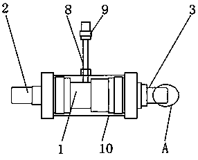
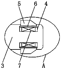
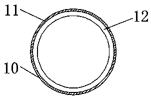
[0023] refer to Figure 1-3 , an axial torque sensor, comprising a sensor body 1 and a protective case 10, one end of the sensor body 1 is fixedly mounted with a first joint 2, the other end of the sensor body 1 is fixedly mounted with a second joint 3, and the outer surface of the second joint 3 A telescopic slot 4 is opened, and the inside of the telescopic slot 4 is movably connected with a top plate 5, and one end of the top plate 5 is located inside the telescopic slot 4, and a limit plate 6 is fixedly installed, and the inner wall of the telescopic slot 4 is fixedly connected with a spring 7, and the sensor body 1 One side of the outer surface is fixedly connected with a connection wire 8 , one end of the connection wire 8 is fixedly connected with a sensor joint 9 , and the protective case 10 is fixedly installed on the outer surface of the sensor body 1 .

[0024] Wherein, one end of the spring 7 is fixedly connected with the limiting plate 6 , the other end of the spr...

Embodiment 2

[0029] refer to Figure 1-2 , 4. An axial moment sensor, comprising a sensor body 1 and a protective case 10, one end of the sensor body 1 is fixedly installed with a first joint 2, the other end of the sensor body 1 is fixedly equipped with a second joint 3, and the second joint 3 The outer surface is provided with a telescopic groove 4, and the inside of the telescopic groove 4 is movably connected with a top plate 5, and one end of the top plate 5 is fixedly installed at a position inside the telescopic groove 4, and a limit plate 6 is fixedly installed, and the inner wall of the telescopic groove 4 is fixedly connected with a spring 7, and the sensor One side of the outer surface of the main body 1 is fixedly connected with a connection wire 8 , one end of the connection wire 8 is fixedly connected with a sensor connector 9 , and the protective case 10 is fixedly installed on the outer surface of the sensor main body 1 .

[0030] Wherein, one end of the spring 7 is fixedly...


PUM


Abstract

The invention discloses an axis torque sensor. The sensor comprises a sensor main body and a protective shell, a first joint is fixedly mounted at one end of the sensor main body, a second joint is fixedly mounted at the other end of the sensor main body, a telescopic groove is formed in the outer surface of the second joint, a top plate is movably connected to the interior of the telescopic groove, a limiting plate is fixedly mounted at the position, located in the telescopic groove, of one end of the top plate, the inner wall of the telescopic groove is fixedly connected with a spring, the outer surface of one side of the sensor main body is fixedly connected with a connecting wire, one end of the connecting wire is fixedly connected with a sensing connector, the protective shell is fixedly installed on the outer surface of the sensor main body, and one end of the spring is fixedly connected with the limiting plate. The safety of the sensor can be improved, the service life of the sensor is prolonged, the sensor can be conveniently installed and used, the using effect of the sensor is improved, and practicability is achieved.

Description

technical field [0001] The invention relates to the technical field of sensors, in particular to a shaft torque sensor. Background technique [0002] The torque sensor is the detection of torsional torque perception on various rotating or non-rotating mechanical parts. The torque sensor converts the physical change of the torque into an accurate electrical signal. The shaft torque sensor is widely used in electric bicycles. The sensor can be used according to the rider's The pedaling force enables the electric device to provide corresponding power support, thereby reducing the rider's riding burden. [0003] The existing axial torque sensor has certain defects in use. The connector of the sensor is inconvenient to connect with the pedal lever on the electric bicycle, and the connection between the sensor and the pedal lever is not firm enough. The sensor has no protective structure during use, and the sensor is vulnerable to damage. The damage caused by the collision of for...

Claims


Application Information

Patent Timeline
IPC IPC(8): G01L5/22B62M6/50
CPCB62M6/50G01L5/225
Inventor 胡刚
Owner 苏州至上软件科技有限公司
Learn More