
A hot-humid climate wind tunnel and its multi-field coupling control system

A wet climate and wind tunnel technology, applied in the direction of control/regulation system, non-electric variable control, and simultaneous control of multiple variables, etc., can solve the problem that multiple test sections cannot be integrated in the same wind tunnel, the scale of the wind tunnel is limited, and it cannot be simulated High temperature, high humidity and complex climate conditions, etc., to improve environmental simulation capabilities, ensure accuracy, and save costs

Active Publication Date: 2020-06-26
SOUTH CHINA UNIV OF TECH +1
View PDF11 Cites 0 Cited by
  • Summary
  • Abstract
  • Description
  • Claims
  • Application Information

AI Technical Summary

Problems solved by technology

However, at present, wind tunnels at home and abroad cannot reproduce the complex and extremely saline hot-humid island climate, so higher requirements are put forward for the environmental simulation capabilities of wind tunnels
[0003] Most of the existing environmental wind tunnels are not suitable for extreme hot and humid climates, and cannot simulate complex climate conditions such as high temperature, high humidity, high salinity, and high radiation, and cannot realize the diurnal and hourly adjustment and dynamic coupling control of multiple environmental parameters. Conducive to fine research of building materials under the coupling influence of complex climate parameters
In addition, the scale of the existing environmental wind tunnel is limited, and it only has partial simulation experiment capabilities, and it is impossible to integrate multiple test sections in the same wind tunnel

Method used


Image

  • A hot-humid climate wind tunnel and its multi-field coupling control system
  • A hot-humid climate wind tunnel and its multi-field coupling control system
  • A hot-humid climate wind tunnel and its multi-field coupling control system

Examples


Embodiment Construction

[0027] The present invention will be further described in detail below in conjunction with the embodiments and the accompanying drawings, but the embodiments of the present invention are not limited thereto.

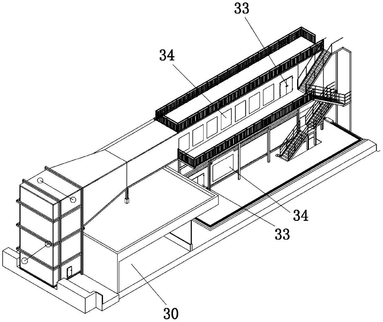
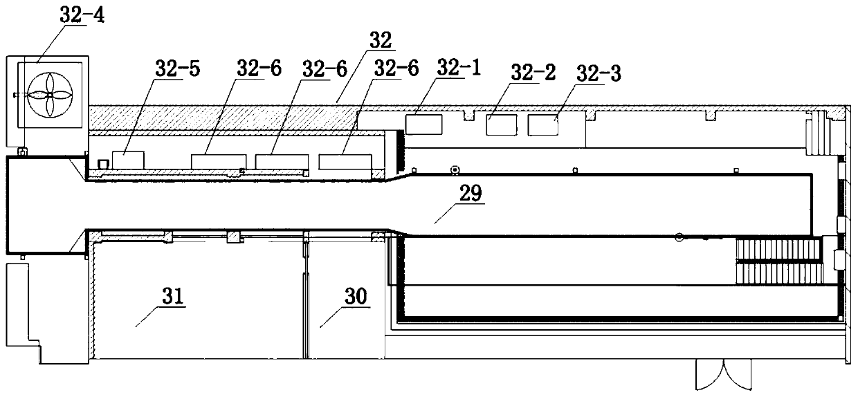
[0028] Such as Figure 1-2 As shown, a hot and humid climate wind tunnel includes a wind tunnel body, a control room, a material room, and an equipment area. The wind tunnel body is set in the middle, the control room and the material room are on the same side of the wind tunnel body and adjacent to the left and right, and the equipment area is opposite to the control room and the material room on the other side of the wind tunnel body. The control room is used to place the computer of the wind tunnel control system and some experimental data acquisition units. The material room is used to store the material components and models required for wind tunnel experiments, so that they can be taken and replaced directly during wind tunnel experiments, saving time and material...


PUM


Abstract

The invention discloses a hot-humid climate wind tunnel and its multi-field coupling control system. Fans, temperature-changing equipment, humidifying equipment, salt spray generators, sky background radiation panels, solar radiation lamp arrays and rainfall are installed in the wind tunnel. Generator, and wind speed sensor, temperature sensor, humidity sensor, salt spray concentration sensor, background radiation temperature sensor, hemispherical radiometer and rain gauge are installed in the test section; the sky background radiation plate is installed on the top of the wind tunnel test section, and the solar radiation The light array and the rainfall generator are installed on the sky background radiant plate; the sky background radiant plate includes heat conduction plates, stainless steel plates, and copper tubes. Multiple heat conduction plates are divided into multiple rows and installed on stainless steel plates, and each row of heat conduction plates is covered with copper Pipes, copper pipes are connected with external hot and cold water equipment. The invention can realize the simulation of seven parameter fields of wind speed, temperature, humidity, solar irradiance, effective sky temperature, rainfall and salt fog in outdoor natural climate.

Description

technical field [0001] The invention relates to the field of multi-parameter environment simulation, in particular to a hot-humid climate wind tunnel and a multi-field coupling control system thereof. Background technique [0002] With the rapid expansion of cities and the extensive application of hard paving materials, the urban heat island effect has become increasingly serious, affecting the regional climate in which residents live. Deteriorating climate conditions not only affect people's physical health and thermal comfort, but also affect the healthy development of the entire city. Reducing the intensity of urban heat island and improving urban thermal environment have attracted the attention of various countries. At the same time, under the current situation that countries are vigorously developing island construction, the thermal and physical properties of island buildings urgently need to be further studied. Among them, wind tunnel test has become an important met...

Claims


Application Information

Patent Timeline
Patent Type & Authority Patents(China)
IPC IPC(8): G01M9/02G01M9/08G05D27/02
CPCG01M9/02G01M9/08G05D27/02G01M9/04G01M9/065
Inventor 孟庆林李令令魏少良
Owner SOUTH CHINA UNIV OF TECH
Learn More