Charging interface protection structure and electronic equipment

A technology of protective structure and charging interface, applied in the direction of connection, circuit, electrical components, etc., can solve the problems of inconvenient disassembly of equipment, reduce equipment production efficiency, difficult maintenance, etc., and achieve effective shielding and exposure, effective waterproof and dustproof protection. Effect

Active Publication Date: 2020-01-21
GOERTEK INC
View PDF6 Cites 2 Cited by
  • Summary
  • Abstract
  • Description
  • Claims
  • Application Information

AI Technical Summary

Problems solved by technology

[0002] At present, most interfaces (such as USB charging interface) do not have a sealing function. If there is a sealing requirement, it is usually sealed by dispensing glue between the interface and the socket of the device shell. After dispensing, the device is inconvenient to disassemble, making maintenance difficult, and many The dispensing process is eliminated, increasing cost input and reducing equipment production efficiency

Method used


Image

  • Charging interface protection structure and electronic equipment
  • Charging interface protection structure and electronic equipment
  • Charging interface protection structure and electronic equipment

Examples


Embodiment 1

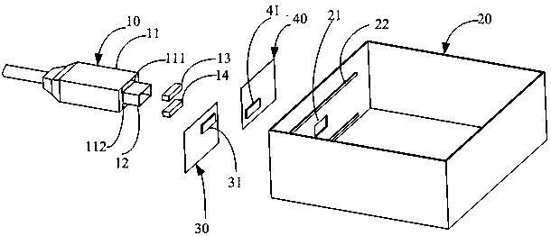
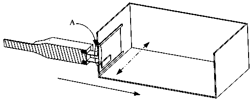
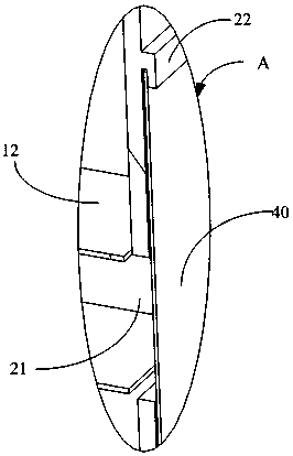
[0025] The protective structure of the charging interface in this embodiment includes a charging plug 10, a housing 20, a first door 30 and a second door 40, the charging plug 10 includes an insertion part 12 and a hand-held part 11, and a magnetic unit is arranged in the hand-held part 11; the housing 20 Specifically, a charging socket 21 for receiving the insertion part 12 is opened on the side wall, and a slide rail 22 is provided on the side wall; a first magnetic part 31 is provided on the first door 30, and a second magnetic part is provided on the second door 40 41. In this embodiment, the first magnetic parts 31 and the second magnetic parts 41 are arranged in parallel and staggered, and the opposite ends of the two are opposite in polarity; when the insertion part 12 is close to the socket 21, the first door 30 and the second door 40 slide along the The rail 22 slides away from the back to expose the socket 21 , and when the insertion portion 12 moves away from the soc...

Embodiment 2

[0038] A magnetic element is arranged on one side (i.e., the upper side or the lower side) of the root of the insertion portion 12 in the handle 11, for example, the magnetic element is the fourth magnetic piece 14 arranged on the lower side of the root of the insertion portion 12, the first The relationship among the magnetic element 31 , the second magnetic element 41 and the fourth magnetic element 14 is the same as that described in the first embodiment above, and will not be repeated here.

Embodiment 3

[0040] Slide rail 22 can be along perpendicular to figure 2 Arranged longitudinally in the dotted line arrow direction, correspondingly, the first magnetic member 31 on the first door 30 and the second magnetic member 41 on the second door 40 are parallel and staggered, and their length direction is the same as that of the first door 30 and the second The opening and closing directions of the door 40 are all perpendicular to figure 2 The direction of the dotted arrow in . Correspondingly, the third magnetic piece 13 and the fourth magnetic piece 14 are arranged on the opposite sides (ie left and right) of the root of the insertion portion 12 in the handle 11, and the first magnetic piece 31, the second magnetic piece 41. The relationship between the third magnetic component 13 and the fourth magnetic component 14 is similar to that described in the first embodiment above, and will not be repeated here.

[0041] It should be noted that the vertically arranged sliding rails ...


PUM


Abstract

The invention relates to a charging interface protection structure and electronic equipment. The charging interface protection structure comprises a charging plug, a shell, a first door and a second door; the charging plug comprises an insertion part and a handheld part, and a magnetic unit is arranged in the handheld part; a charging socket used for receiving the insertion part is formed in the shell, and a first magnetic part is arranged on the first door; a second magnetic part is arranged on the second door, wherein the polarities of the opposite ends of the first magnetic part and the second magnetic part are opposite; when the insertion part is close to the charging socket, the magnetic unit generates a repulsive force with the first magnetic part and the second magnetic part, so thefirst door and the second door are away from each other to expose the charging socket; when the insertion part is away from the charging socket, the first door and the second door attract each otherto get close to shield the charging socket. The protection function of the charging interface of the electronic equipment is realized, and the use safety and reliability of the electronic equipment are improved.

Description

technical field [0001] The invention belongs to the technical field of electronic equipment protection, and in particular relates to a charging interface protection structure and electronic equipment. Background technique [0002] At present, most interfaces (such as USB charging interface) do not have a sealing function. If there is a sealing requirement, it is usually sealed by dispensing glue between the interface and the socket of the device shell. After dispensing, the device is inconvenient to disassemble, making maintenance difficult, and many The dispensing process is eliminated, increasing cost input and reducing equipment production efficiency. Therefore, there is a need for a novel waterproof and dustproof protective structure for an interface of an electronic device, so as to improve the protective performance of the interface. Contents of the invention [0003] The invention provides a charging interface protection structure and electronic equipment, which re...

Claims


Application Information

Patent Timeline
Patent Type & Authority Applications(China)
IPC IPC(8): H01R13/52
CPCH01R13/5213
Inventor 李新
Owner GOERTEK INC
Why Eureka
Try Eureka