Device for twisting end of stator of flat wire motor

A motor stator and flat wire technology, which is applied in the direction of electromechanical devices, motor generators, electrical components, etc., can solve the problems of increasing the manufacturing cost of flat wire stators, and the inability to ensure that the end of the stator is even, so as to reduce the number of equipment, Space-saving, flat wire ends flush

Active Publication Date: 2020-01-24
HEFEI JUYI POWER SYST CO LTD
View PDF4 Cites 9 Cited by
  • Summary
  • Abstract
  • Description
  • Claims
  • Application Information

AI Technical Summary

Problems solved by technology

[0002] In the prior art, the method of twisting the end of the flat wire motor stator for new energy vehicles is as follows: before the flat wire stator starts to twist, it needs to carry out end shaping and flaring process to ensure that the flat wire can be inserted into the twisting mold or needs to be twisted. Manually insert the wire into the tooling mold, and after turning the head, the wire ends at the end of the stator cannot be guaranteed to be even, and it is necessary to perform alignment work to meet the welding requirements
[0003] As the new energy vehicle drive motor flat wire stator requires more and more flat wire layers (currently 8 layers), the corresponding twisting tooling is also increasing. For flat wire forming, shaping, flaring and twisting before twisting The requirements for the first-class technology are getting higher and higher, and more technology makes the manufacturing cost of the flat wire stator greatly increased.

Method used


Image

  • Device for twisting end of stator of flat wire motor
  • Device for twisting end of stator of flat wire motor
  • Device for twisting end of stator of flat wire motor

Examples


Embodiment Construction

[0042] The embodiments of the present invention are described in detail below. This embodiment is implemented on the premise of the technical solution of the present invention, and detailed implementation methods and specific operating procedures are provided, but the protection scope of the present invention is not limited to the following implementation example.

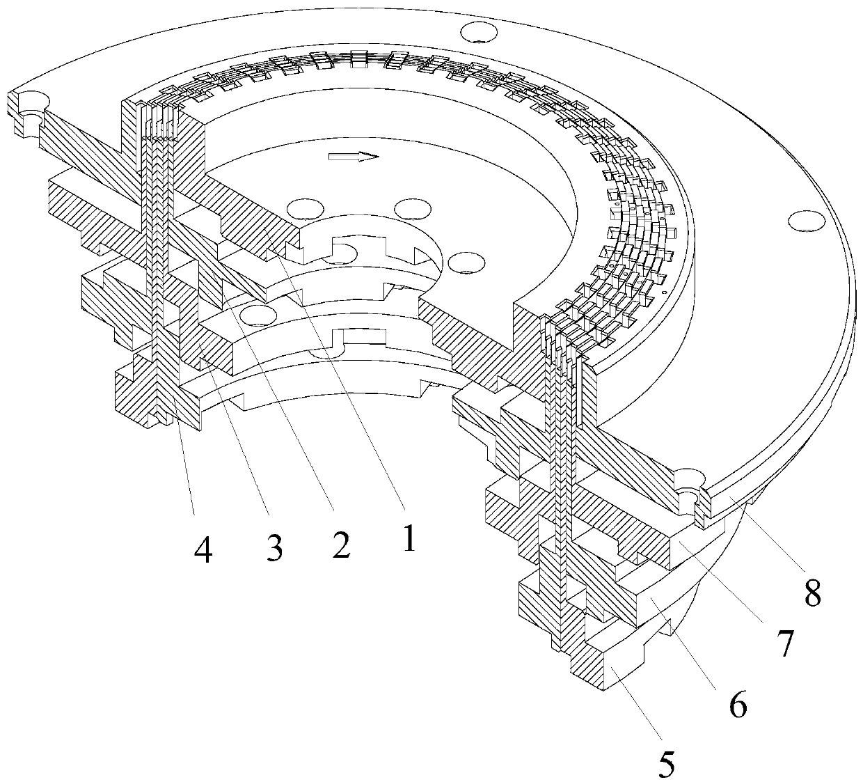
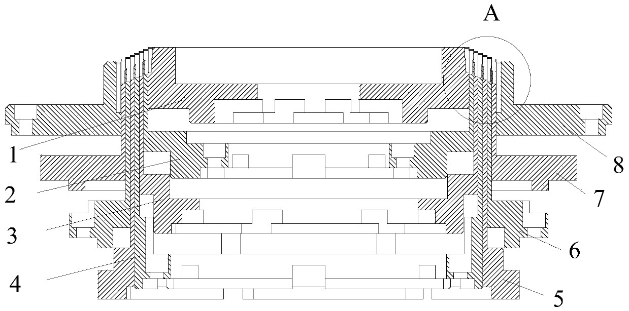
[0043] see Figure 1 to Figure 24 , this embodiment discloses a device for twisting the end of a flat wire motor stator. Working ring 9, the working rings 9 of each mold are arranged coaxially from inside to outside in the radial direction, the molds located in the innermost ring and the outermost ring are respectively the inner ring mold 1 and the outer ring mold 8, and the molds in the middle part are middle mold,

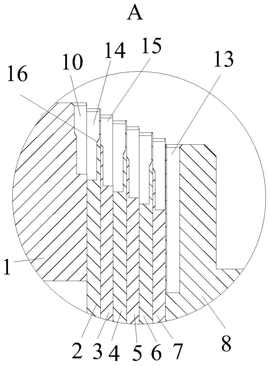
[0044] The upper end surface of the working ring 9 of the inner ring mold 1 is provided with a plurality of inner ring slots along the circumferential direction, and the plurality of inner ring slot...


PUM


Abstract

The invention discloses a device for twisting the end of a stator of a flat wire motor. The device comprises an even number of molds which are sequentially nested in the radial direction. Multiple inner slots are formed in the upper end face of a working ring of an inner mold in the circumferential direction, wherein the outer sides of one part of the inner slots are opened to form first-class inner slots, and the outer sides of the other part of the inner slots are closed to form second-class inner slots. Multiple outer slots are formed in the upper end face of a working ring of an outer moldin the circumferential direction, wherein the inner sides of one part of the outer slots are opened to form first-class outer slots, and the inner sides of the other part of the outer slots are closed to form second-class outer slots. Multiple middle slots are formed in the upper end face of a working ring of each middle mold in the circumferential direction, wherein the inner sides of one part of the middle slots are opened to form first-class middle slots, and the outer sides of the other part of the middle slots are closed to form second-class middle slots. The upper end faces of the working rings of all the molds are distributed in a gradually-reduced step shape from inside to outside. The device has the advantages that the process steps are reduced and the cost is saved.

Description

technical field [0001] The invention relates to a stator end twisting device, in particular to a device for flat wire motor stator end twisting. Background technique [0002] In the prior art, the method of twisting the end of the flat wire motor stator for new energy vehicles is as follows: before the flat wire stator starts to twist, it needs to carry out end shaping and flaring process to ensure that the flat wire can be inserted into the twisting mold or needs to be twisted. Manually insert the wire into the tooling mold, and after twisting the head, the wire end at the end of the stator cannot be guaranteed to be even, so it is necessary to perform alignment work to meet the welding requirements. [0003] As the new energy vehicle drive motor flat wire stator requires more and more flat wire layers (currently 8 layers), the corresponding twisting tooling is also increasing. For flat wire forming, shaping, flaring and twisting before twisting The requirements for the po...

Claims


Application Information

Patent Timeline
Patent Type & Authority Applications(China)
IPC IPC(8): H02K15/00
CPCH02K15/0087
Inventor 刘蕾石爱文吴洋汪波沐俊宏
Owner HEFEI JUYI POWER SYST CO LTD
Why Eureka
Try Eureka