
Electric hammer cylinder

A technology of air cylinder and electric hammer, applied in the direction of striking tools, light impact tools, manufacturing tools, etc., can solve the problems of broken connecting ears, affecting the overall use of the electric hammer, broken connecting holes, etc., to prevent root breakage and enhance the smoothness of movement. , the effect of increasing the service life

Pending Publication Date: 2020-01-31
温岭市百邦电动工具配件厂(普通合伙)
View PDF1 Cites 0 Cited by
  • Summary
  • Abstract
  • Description
  • Claims
  • Application Information

AI Technical Summary

Problems solved by technology

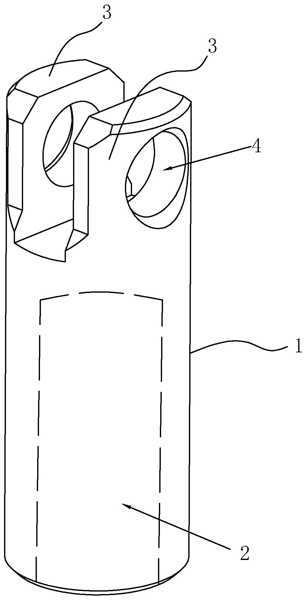
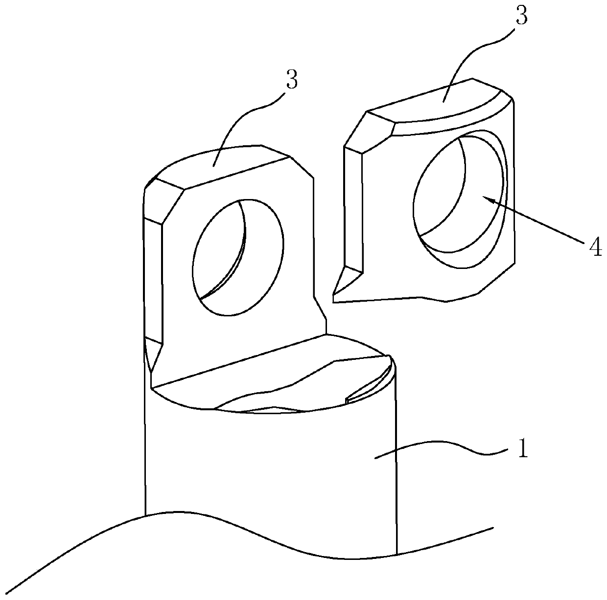
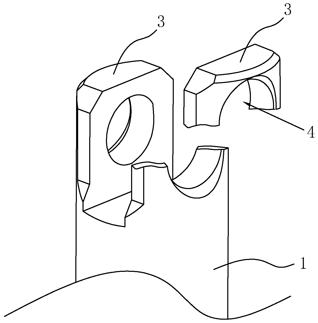
see figure 2 and 3 , the traditional electric hammer cylinder is prone to transverse fracture of the connecting hole 4 and the root of the connecting ear 3, which seriously affects the overall use of the electric hammer

Method used


Image

  • Electric hammer cylinder
  • Electric hammer cylinder
  • Electric hammer cylinder

Examples


Embodiment 1

[0039] Embodiment 1, an electric hammer cylinder:

[0040] as attached Figure 4~7 The shown electric hammer cylinder includes a cylinder body 1, one end of the cylinder body 1 is provided with a cylinder hole 2, and the other end is provided with two connection ears 3, and the two connection ears 3 are provided with a coaxial connection hole 4. The tops of the connecting ears 3 are connected as a whole through the connecting plate 5 . Wherein, the middle part of the lower surface of the connecting plate 5 is flush with the top of the connecting hole 4 , and the two sides of the connecting plate 5 are provided with a first relief notch 6 which is inclined upward on the outside. The first relief notch 6 reserves necessary space for the swing of the fork to prevent the fork from colliding with the connecting plate 5 . Here, the connecting plate 5 and the cylinder body 1 are originally integrated, and the feature of the connecting plate 5 is formed during the cylinder processin...

Embodiment 2

[0048] Embodiment 2, an electric hammer cylinder:

[0049] See attached Figure 8 The difference between the second embodiment and the first embodiment is that an oil storage tank 8 is provided on the outer surface of the cylinder body 1, the length direction of the oil storage tank 8 is arranged along the axial direction of the cylinder body 1, and the oil storage tanks 8 are evenly distributed in the circumferential direction The outer circle of the cylinder body 1. The oil storage tank 8 can store grease or oil, and provide lubrication to the cylinder 1 when the cylinder 1 moves.

Embodiment 3

[0050] Embodiment 3, an electric hammer cylinder:

[0051] See attached Figure 9 The difference between the third embodiment and the second embodiment is that the oil storage tank 8 is a spiral groove extending axially around the cylinder body 1 . The spiral groove surrounds the cylinder body 1, which can fully lubricate the cylinder body 1, and at the same time, the consumption of grease or oil is slow.


PUM


Abstract

The invention provides an electric hammer cylinder, and belongs to the field of electric tools. The electric hammer cylinder comprises a cylinder block; a cylinder hole is formed in one end of the cylinder block, and two connecting lugs are arranged at the other end; coaxial connecting holes are formed in the two connecting lugs; the tops of the two connecting lugs are connected as a whole througha connecting plate; and the roots of the two connecting lugs are connected as a whole, and are transited through arcs. The tops and the roots of the two connecting lugs are connected as a whole, so that the structural strength is greatly improved; meanwhile, the connecting places are transited by the arcs, the roots of the connecting lugs and the transverse direction of the connecting holes are effectively prevented from rupturing; the service life of the electric hammer cylinder is far longer than the service life of other parts of an electric hammer; and even if the other parts of the electric hammer cylinder are damaged and replaced, the electric hammer cylinder cannot generate the damage and replacement phenomenon.

Description

technical field [0001] The invention relates to the field of electric tools, in particular to an electric hammer cylinder. Background technique [0002] An electric hammer is a commonly used electric tool. The electric hammer cylinder is a key part of the electric hammer, which is usually made of aluminum. See the patent that CN202241182U is called a kind of single-knob four-function electric hammer with the notification number, and its electric hammer includes an impact shaft, a cylinder, a motor shaft and a swing rod bearing, and the cylinder is arranged on the impact shaft and is connected with the swing rod bearing. The cylinder assembly realizes reciprocating motion in the inner hole of the rotating sleeve through the back and forth swing of the swing rod in the swing rod bearing. [0003] The traditional electric hammer cylinder is attached figure 1 As shown, it includes a cylinder body 1, one end of the cylinder body 1 is provided with a cylinder hole 2, and the ot...

Claims


Application Information

Patent Timeline
Patent Type & Authority Applications(China)
IPC IPC(8): B25D17/00B25D11/00
CPCB25D17/00B25D11/00
Inventor 林文焕
Owner 温岭市百邦电动工具配件厂(普通合伙)
Learn More