
Forced mixer

A technology of forced mixer and stirring teeth, which is applied to cement mixing devices, clay preparation devices, cleaning hollow objects, etc., can solve the problems of limited stirring teeth, waste of electric energy, insufficient stirring, etc.

Pending Publication Date: 2020-01-31
CHONGQING JURONG CONSTR GRP
View PDF0 Cites 0 Cited by
  • Summary
  • Abstract
  • Description
  • Claims
  • Application Information

AI Technical Summary

Problems solved by technology

[0002] Under the existing technical conditions, the concrete mixing equipment used in the construction process all adopts the working mode of single-shaft mixing. This working mode can drive only a limited number of mixing teeth, and it is easy to cause insufficient mixing. Therefore, it is necessary to It takes a long time to mix the concrete well. This method affects work efficiency and wastes electric energy. Moreover, the existing device lacks a cleaning function. The residual concrete in the device is not suitable for cleaning, which will easily lead to the formation of concrete agglomerates in the device and affect its reuse. In view of Therefore, after in-depth research on the above-mentioned problems, this case came into being

Method used


Image

  • Forced mixer
  • Forced mixer
  • Forced mixer

Examples


Embodiment Construction

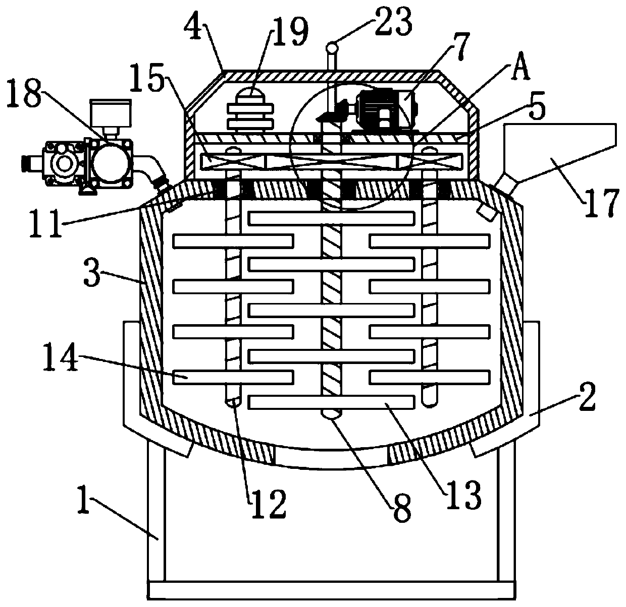
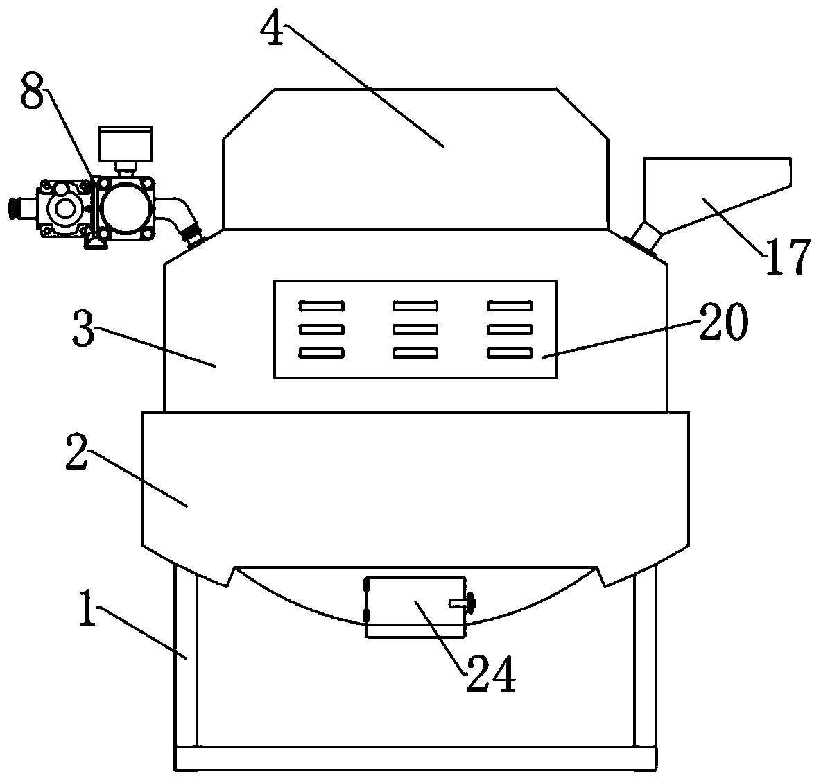
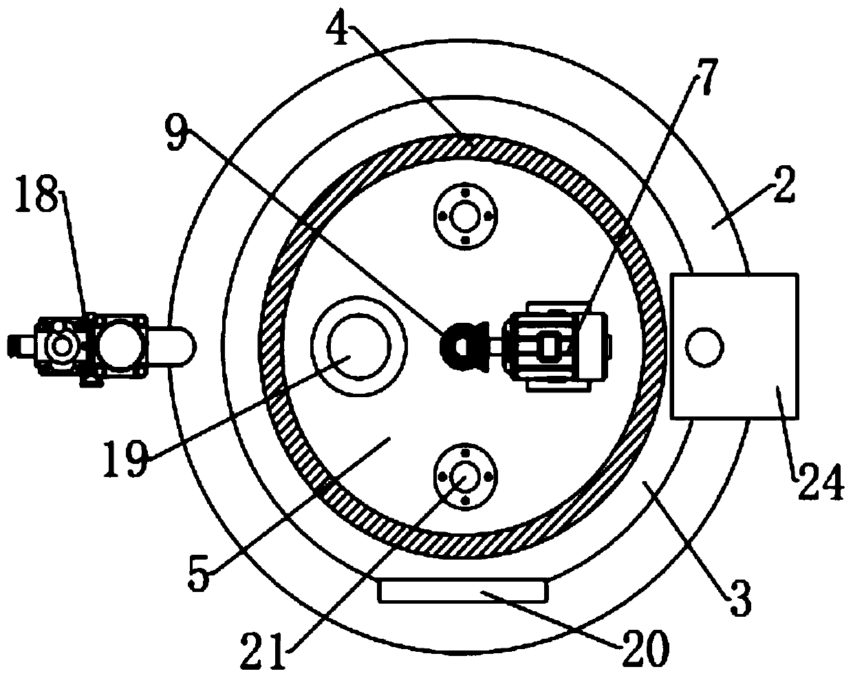
[0031] The present invention is specifically described below in conjunction with accompanying drawing, as Figure 1-5 As shown, a forced mixer includes a bracket and a shroud, the shroud is installed on the bracket, a power structure and a stirring structure are installed on the shroud, a spray structure is installed on the power structure; the power The structure mainly includes: main box body, auxiliary box body and power unit; the main box body is installed on the coaming, the auxiliary box body is installed on the upper wall of the main box body, and the power unit is installed on the main box body The power part mainly includes: a mounting plate, a first bearing and a power assembly; the mounting plate is horizontally installed on the opposite wall of the auxiliary box, the first bearing is embedded on the mounting plate, and the power assembly is installed on the On the wall surface of the mounting plate; the power assembly mainly includes: a servo motor, a first rotatin...


PUM


Abstract

The invention discloses a forced mixer. The mixer comprises a supporting frame and a surrounding plate, wherein the surrounding plate is arranged on the supporting frame, a power structure and a stirring structure are arranged on the surrounding plate, and a spraying structure is arranged on the power structure; and the power structure mainly comprises a main box body, an auxiliary box body and apower part, wherein the main box body is arranged on the surrounding plate, the auxiliary box body is arranged on the upper wall surface of the main box body, and the power part is arranged on the main box body. The mixer has the beneficial effects that the mixer is researched and improved from the aspect of structure, a second gear and a third gear are added to coordinate work, a first rotating rod and a second rotating rod are driven to rotate to drive more stirring teeth to operate, staggered moving is achieved, so that mixing is more uniform, the working efficiency is high, and the time and energy are saved; and a spraying head is arranged in the mixer, so that the mixer has a cleaning function, and the mixer is convenient to clean after mixing.

Description

technical field [0001] The invention relates to the field of concrete mixing equipment, in particular to a forced mixer. Background technique [0002] Under the existing technical conditions, the concrete mixing equipment used in the construction process adopts the working method of single-shaft mixing. This working method can drive only a limited number of mixing teeth, and it is easy to cause insufficient mixing. Therefore, it is necessary to It takes a long time to mix the concrete well. This method affects work efficiency and wastes electric energy. Moreover, the existing device lacks a cleaning function. The residual concrete in the device is not suitable for cleaning, which will easily cause concrete agglomeration in the device and affect its reuse. In view of Therefore, after in-depth research on the above-mentioned issues, this case came into being. Contents of the invention [0003] The purpose of the present invention is in order to solve the above-mentioned pro...

Claims


Application Information

Patent Timeline
IPC IPC(8): B28C5/16B28C5/08B08B9/093
CPCB08B9/0813B28C5/0806B28C5/0831B28C5/16
Inventor 梁华国梁华勇
Owner CHONGQING JURONG CONSTR GRP
Learn More