
Charging bow and charging device

A technology of charging device and charging bow, which is applied in the direction of current collectors, electric vehicles, power collectors, etc., can solve the problems of incomplete contact and large energy loss, and achieve the effect of easy assembly

Pending Publication Date: 2020-01-31
ZHENGZHOU YUTONG BUS CO LTD
View PDF7 Cites 0 Cited by
  • Summary
  • Abstract
  • Description
  • Claims
  • Application Information

AI Technical Summary

Problems solved by technology

[0004] The purpose of the present invention is to provide a charging bow, aiming to solve the problem in the prior art that the charging bow cannot completely contact with the current collector of the tilting vehicle, resulting in large energy loss; the purpose of the present invention is also to provide a charging bow equipped with the above Charging device for charging bow

Method used


Image

  • Charging bow and charging device
  • Charging bow and charging device
  • Charging bow and charging device

Examples


Embodiment Construction

[0034] Embodiments of the present invention will be further described below in conjunction with the accompanying drawings.

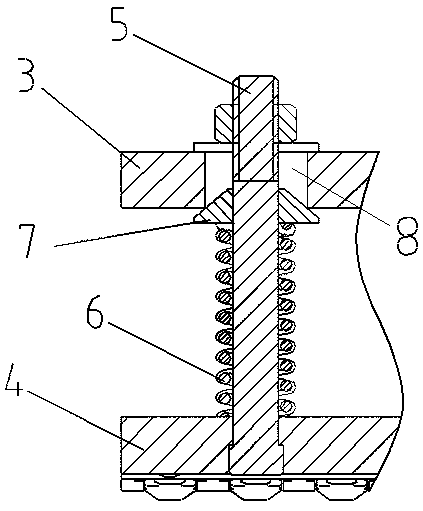
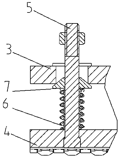
[0035] Specific embodiment one of the charging bow of the present invention, such as Figure 1 to Figure 6 As shown, it includes the charging bow support and the pole plate 4 arranged at intervals up and down, and there is an elastic buffer between the pole plate 4 and the charging bow support to provide the separation force between the charging bow support and the pole plate 4 . Define the length direction of the pole plate 4 as the left-right direction, and the width direction of the pole plate 4 as the front-rear direction. The charging bow bracket includes a charging bow fixing frame 1 , an insulating connector 2 and a mounting plate 3 arranged in sequence from top to bottom. There are four pole plates 4, and the four pole plates 4 are connected to the four corners of the lower end of the charging bow bracket through anti-slip connectors. The elast...


PUM


Abstract

The invention relates to a charging bow and a charging device. The charging bow comprises charging bow brackets and pole plates, wherein the charging bow brackets and the pole plates are arranged at intervals, and an elastic buffer piece for providing separation force for each charging bow bracket and each pole plate is arranged between each charging bow bracket and each pole plate. The charging bow also comprises anti-falling connecting pieces used for connecting the charging bow brackets with the pole plates and tightly pressing the elastic buffer pieces between the charging bow brackets andthe pole plates; each charging bow bracket and / or pole plate is provided with penetration holes used for enabling each anti-falling connecting piece to penetrate; and at least one penetration hole and each anti-falling connecting piece have a certain floating gap in a front and back and / or left and right direction to enable each anti-falling connecting piece to swing in the front and back and / or left and right direction. When the charging bow disclosed by the invention is used for charging an aslant-parking vehicle, the pole plate can realize total contact with a vehicle current collectiondevice through swinging in the front and back and / or left and right direction as well as vertical floatation, and therefore, the problem in the prior art that the charging bow and the current collection device of the aslant-parking vehicle can not be in the total contact can be solved.

Description

technical field [0001] The invention relates to a charging bow and a charging device. Background technique [0002] With the promotion and popularization of new energy vehicles, the number of electric vehicles is increasing, especially in the field of urban public transportation, more and more buses are powered by electricity. Electric vehicles need to be recharged just like traditional cars need to be refueled. At present, most household electric vehicles in China use charging guns to realize the electrical connection between charging equipment and vehicles. However, the battery capacity of electric buses is large, and it takes a long time to charge using traditional charging guns, which is difficult to apply to electric buses that require fast charging. In order to meet the demand for fast charging of electric buses, electric buses in the prior art generally use a charging bow capable of carrying a large current to be electrically connected to a current collector on the ...

Claims


Application Information

Patent Timeline
Patent Type & Authority Applications(China)
IPC IPC(8): B60L5/22B60L5/30
CPCB60L5/22B60L5/30
Inventor 窦红伟
Owner ZHENGZHOU YUTONG BUS CO LTD
Learn More