Radial-flow steam turbine

A steam turbine and radial flow technology, applied in the field of steam turbines, can solve the problems of low operation safety, stability and reliability, high blade processing requirements, long processing cycle, etc., to achieve safety, stability and reliability, low raw material consumption, high-speed rotation and good rigidity Effect

Active Publication Date: 2007-09-12
黄少斌 +2
View PDF9 Cites 0 Cited by
  • Summary
  • Abstract
  • Description
  • Claims
  • Application Information

AI Technical Summary

Problems solved by technology

Under small flow rate, the thermal efficiency is low, the structure is complex, the blade processing requirements are high, the processing cycle is long, the cost is high, and the operation and maintenance requirements are strict. Since the impeller and the blade are connected by assembly, the rigidity is poor, and the operation safety, stability and reliability are not high. Accidents are prone to occur in practical applications, resulting in varying degrees of economic losses, and even serious machine damage losses

Method used


Image

  • Radial-flow steam turbine
  • Radial-flow steam turbine
  • Radial-flow steam turbine

Examples


Embodiment Construction

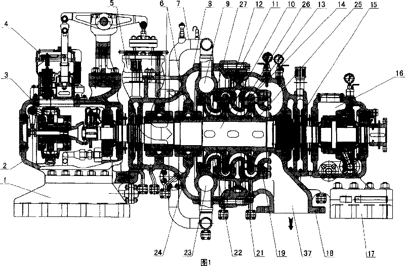
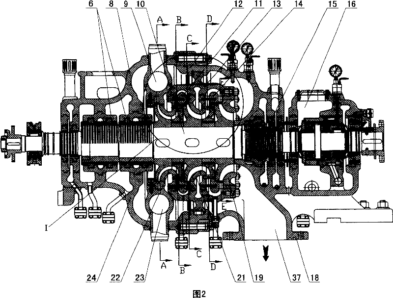
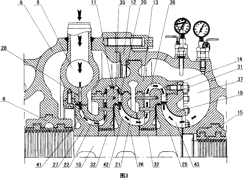
[0039] As shown in Figures 1-17, the radial steam turbine in this preferred embodiment includes a cylinder, a stator and a rotor.

[0040] As shown in Fig. 1-3, the stator and the rotor are arranged in the cylinder, and the complete steam channel formed by the cylinder, the stator and the rotor is provided in the cylinder to make the steam flow directionally, including the steam inlet pipe 7, the steam inlet chamber, centripetal energy conversion channel group, steam flow reversing channel group and exhaust chamber 37, wherein the number of centripetal energy conversion channel groups is 3, which are respectively the first centripetal energy conversion channel group 41, The second centripetal energy conversion flow channel group 42, the third centripetal energy conversion flow channel group 43, the number of steam flow reversing flow channel groups is 2, respectively the first steam flow reversing flow channel group 35, the second The steam flow reversing flow channel group 36...


PUM


Abstract

A radial-flow turbine containing cylinder, stator and rotor installed in cylinder, featuring a complete steam flow path, steam admission pipe, steam admission chamber, at least two or plurality of endiocentric energy converting flow path groups, at least one steam flow reversible flow path group and exhausting chamber, wherein the number of steam flow reversible flow path group is one less then that of endiocentric energy converting flow path groups, all endiocentric energy converting flow path groups and steam flow reversible flow path group are alternately arranged along axial direction of rotor, plurality of convergent nozzles are set at the outlet of steam admission chamber and end of flow reversible flow path groups, comparing with current technology. Said invention has advantages of high energy conversion efficiency and fine anti overspeed, anti vibration and shock resistance performance.

Description

technical field [0001] The invention relates to a steam turbine, in particular to a radial flow steam turbine which uses the impulsive force generated by the diffuser expansion centripetal injection of the converging nozzle to drive the rotor to rotate. Background technique [0002] Existing traditional steam turbines that have been widely used in industrial production are mostly vane turbines, including condensing steam turbines, steam extraction condensing steam turbines, back-pressure steam turbines, steam extraction back-pressure steam turbines, steam extraction steam turbines, intermediate reheating steam turbines, etc. , its basic structure is roughly the same, the rotor can be divided into single-stage and multi-stage structures, relying on the expansion of the working medium steam to do work, including steam inlet chamber, nozzle group, blade, impeller, main shaft, stator, exhaust chamber, etc. Under small flow rate, the thermal efficiency is low, the structure is co...

Claims


Application Information

Patent Timeline
Patent Type & Authority Patents(China)
IPC IPC(8): F01D1/06F01D1/22F01D1/28
Inventor 程建平郑群
Owner 黄少斌
Why Eureka
Try Eureka