
Transmission machine for fused silica ceramic roll bar products

A technology of ceramic rollers and fused silica, applied in the direction of conveyors, mechanical conveyors, conveyor objects, etc., can solve the problems of accelerated air drying, inflexible use, and inability to extend the effective length of the conveyor, so as to extend the conveying length and improve The effect of flexibility

Inactive Publication Date: 2020-01-31
安徽恒洋新材料科技有限公司
View PDF7 Cites 4 Cited by
  • Summary
  • Abstract
  • Description
  • Claims
  • Application Information

AI Technical Summary

Problems solved by technology

[0003] The patent document (CN208485247U) discloses a conveyor, which includes a frame, legs, a fixed frame, a roller, a motor, a fan, a baffle, and a belt. There are several legs connected to the frame, and the number of the legs is four , installed on the four corners of the bottom of the frame, a belt is installed on the frame, a number of rollers are installed in the belt, the number of the rollers is 3 to 5, the motor is installed on the feet, The support feet are connected with a fixed frame, the fixed frame is composed of two fixed rods, the fixed rods are fixed by bolts, each of the fixed rods is connected with two diagonally supported legs, and the fixed frame is equipped with Fan, the baffle plate is installed on the frame, the baffle plate includes a notch part, a block part and a fixed part, the baffle plate connected with the frame spreads the material on the conveyor belt individually, the fan is installed on the fixed frame, Accelerated air drying; the conveyor cannot adjust the angle of the transfer part, which is not flexible to use, and the height of the transfer cannot be adjusted, and the effective length of the conveyor cannot be extended

Method used


Image

  • Transmission machine for fused silica ceramic roll bar products
  • Transmission machine for fused silica ceramic roll bar products
  • Transmission machine for fused silica ceramic roll bar products

Examples


Embodiment Construction

[0029] The technical solutions in the embodiments of the present invention will be clearly and completely described below in conjunction with the embodiments of the present invention. Apparently, the described embodiments are only some of the embodiments of the present invention, not all of them. Based on the embodiments of the present invention, all other embodiments obtained by persons of ordinary skill in the art without creative efforts fall within the protection scope of the present invention.

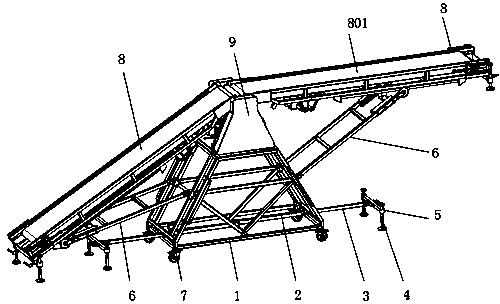
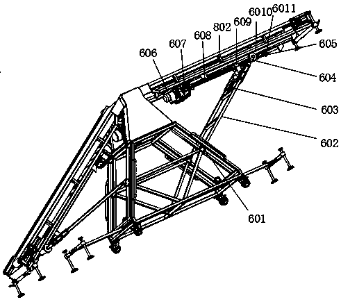
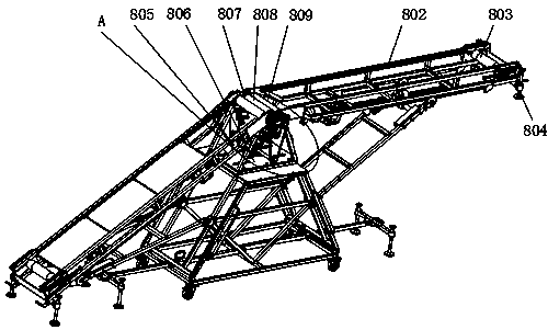
[0030] see Figure 1-5 As shown, a fused silica ceramic roller rod product conveyor includes a support frame 1, the upper surface of the support frame 1 is fixedly equipped with a chain cover 9 near the front and rear ends, and the upper surface of the support frame 1 is located at two A trapezoidal support frame 10 is fixedly installed between the chain covers 9, and a transmission mechanism 8 is movably installed on both sides of the trapezoidal support frame 10, and an adjustme...


PUM


Abstract

The invention discloses a transmission machine for fused silica ceramic roll bar products. The transmission machine for the fused silica ceramic roll bar products comprises a support frame, wherein achain cover is fixedly installed at positions close to a front end and a rear end, of the upper surface of the support frame separately, a trapezoidal support frame is fixedly installed at a positionbetween the two chain covers, of the upper surface of the support frame, a transmission mechanism is movably installed at the two sides of the trapezoidal support frame separately, and an adjustment mechanism is movably installed between the two transmission mechanisms and the support frame separately; and each transmission mechanism comprises a transmission main body, a connection plate is fixedly installed on a front surface and a rear surface close to one end, of the transmission main body separately, and a second roller is rotationally installed between the two connection plates. Accordingto the transmission machine for the fused silica ceramic roll bar products, through the arranged adjustment mechanisms, the inclination angles of the two transmission mechanisms can be adjusted, so that application for the transmission machine to transmission ranges with different heights is facilitated, and the flexibility of the transmission machine is improved; and through the cooperative usefor the two transmission mechanisms, the transmission length of the transmission machine can be prolonged.

Description

technical field [0001] The invention relates to the technical field of roller rod transmission, in particular to a fused silica ceramic roller rod product conveyor. Background technique [0002] Ceramic rollers are installed in the roller cellar for carrying and transporting the magnetic blanks to be fired. [0003] The patent document (CN208485247U) discloses a conveyor, which includes a frame, legs, a fixed frame, a roller, a motor, a fan, a baffle, and a belt. There are several legs connected to the frame, and the number of the legs is four , installed on the four corners of the bottom of the frame, a belt is installed on the frame, a number of rollers are installed in the belt, the number of the rollers is 3 to 5, the motor is installed on the feet, The support feet are connected with a fixed frame, the fixed frame is composed of two fixed rods, the fixed rods are fixed by bolts, each of the fixed rods is connected with two diagonally supported legs, and the fixed frame...

Claims


Application Information

Patent Timeline
Patent Type & Authority Applications(China)
IPC IPC(8): B65G41/00B65G15/58B65G23/04B65G23/30B65G23/22B65G37/00
CPCB65G15/58B65G23/04B65G23/22B65G23/30B65G37/00B65G41/002B65G41/008B65G2201/0232
Inventor 邱滔张俊黄锡清
Owner 安徽恒洋新材料科技有限公司
Learn More